Car

What we’ve learned from exclusive CFD analysis of the 2026 Formula 1 car

by Jack Chilvers

10min read

2026 F1 car 3D model in windtunnel

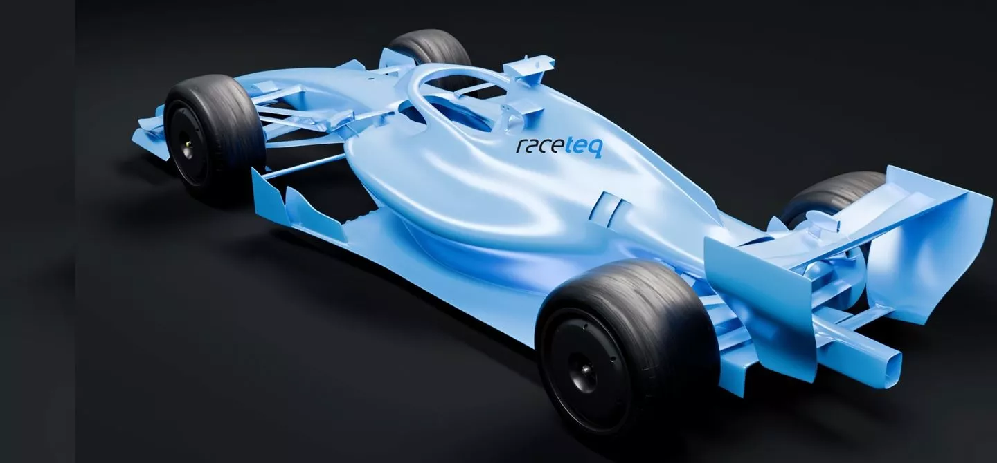
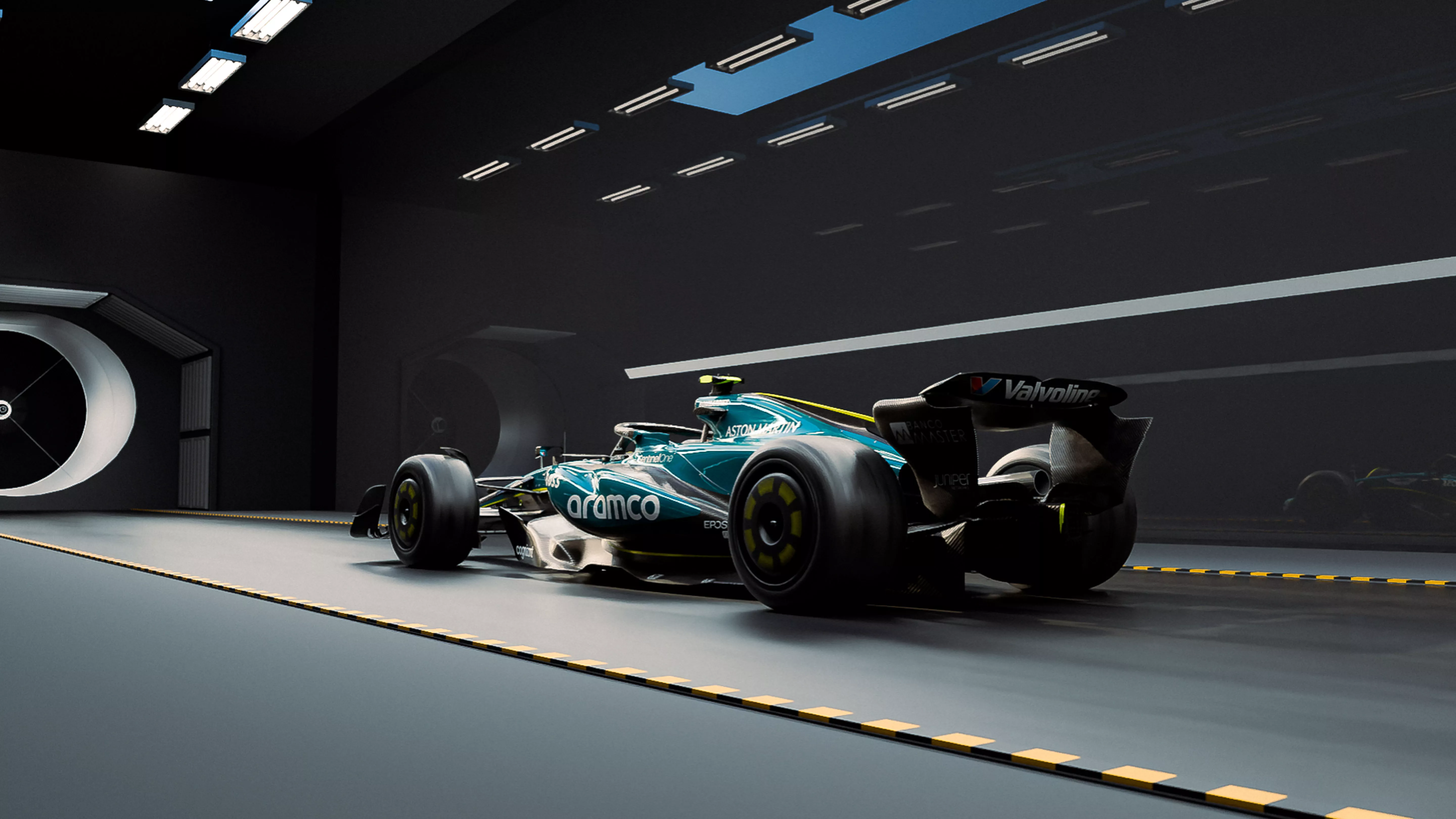
Formula 1 engineers were finally unleashed on the new set of the F1 technical regulations for 2026 at the beginning of 2025, and exclusive computational fluid dynamics (CFD) analysis has provided us insight into how the new cars could behave.

Aston Martin F1 car exiting garage

Sign up for a weekly newsletter and we'll make sure you're fully up-to-date in the world of race technology

While there’s plenty of time and money being invested in the current season, aerodynamicists and engineers back at teams’ respective factories also have their sights set on next year, aiming to hit the ground running with the new 2026 F1 cars.

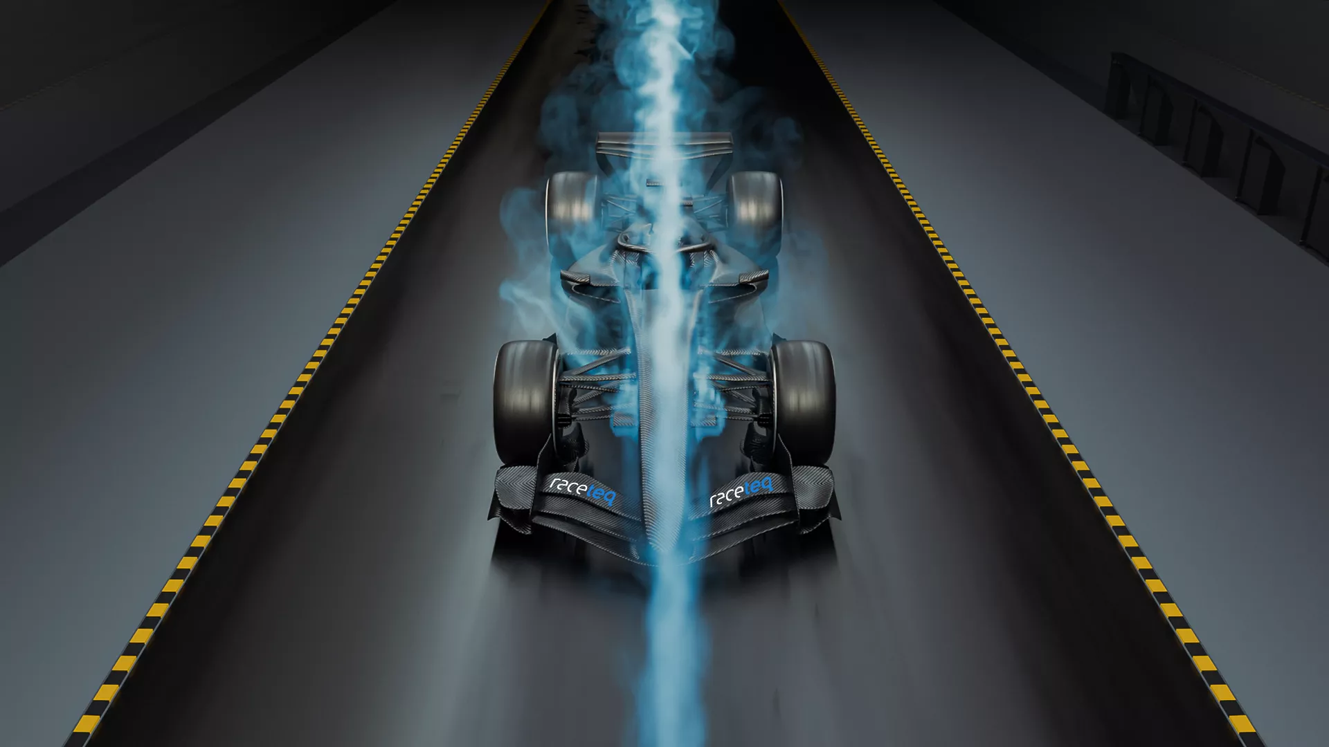
With the help of Bramble CFD using CFD data - often referred to as the ‘virtual windtunnel’ - we can interrogate the airflow around a model of next season’s racecar in detail to better understand the behaviour of the airflow around this new machine.

In a bid to improve wheel-to-wheel racing, the new regulations build on the trend of reducing the available amount of outwash generation - a once-coveted mechanism aerodynamicists employed to push wheel wakes away from the rest of the car and out of harm’s way. 

To achieve this, the front wing has been made narrower, ‘wheel wake control boards’ have been added ahead of the sidepods, and changes have been made to the brake duct geometry around the front wheels.
2026 F1 car model

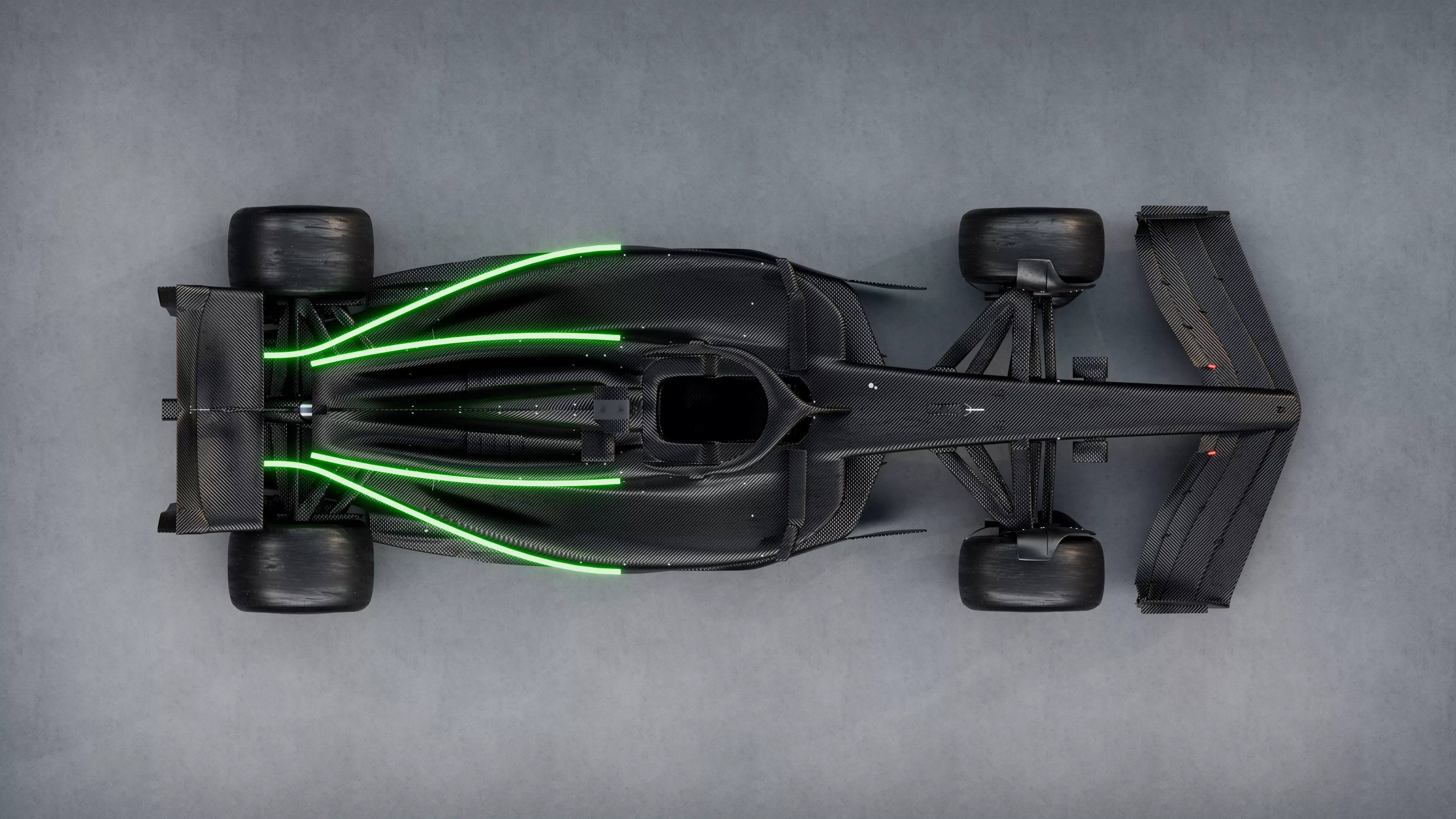
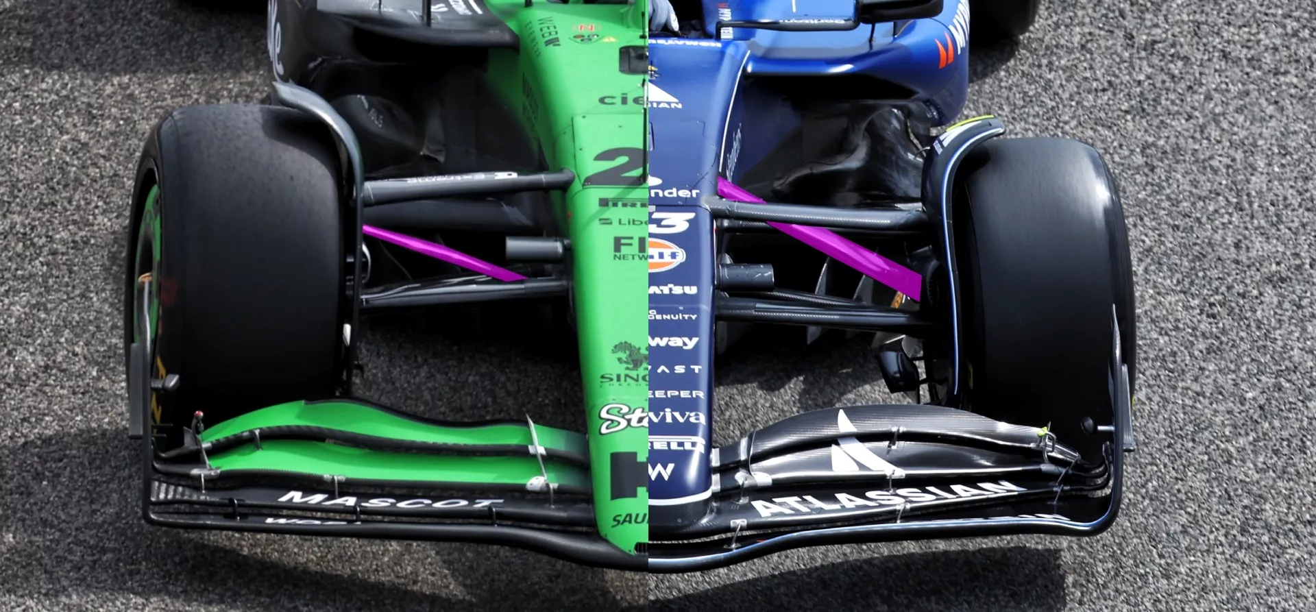
The 2026 F1 car brings boards to the front of the floor to control outwash

Red Bull F1 car 2025

Car

Flexi-wings and skid blocks: The two major technical Formula 1 changes that teams had to make in Spain

The 2026 F1 front wing  

The front wing of an F1 car serves two key purposes. Firstly, it generates load ahead of the front axle to contribute to the overall aerodynamic balance of the car, something which drivers are acutely sensitive to when navigating the grip-limited corners of a circuit. 
 
Secondly, as the first component on the car the airflow arrives at, the front wing must extract load in such a way that the downstream flow is set up to allow as much performance as possible to be extracted by the rest of the car.


As mentioned previously, the generation of outwash (airflow being directed in a direction from the centreline of the car, outwards) has been severely limited in more recent times. 
 

Whilst the use of blown axles and aggressively outwashing front wing endplates is a distant memory, aerodynamicists can employ alternative tactics to help improve the front wheel wake control.
CFD analysis of 2026 F1 car

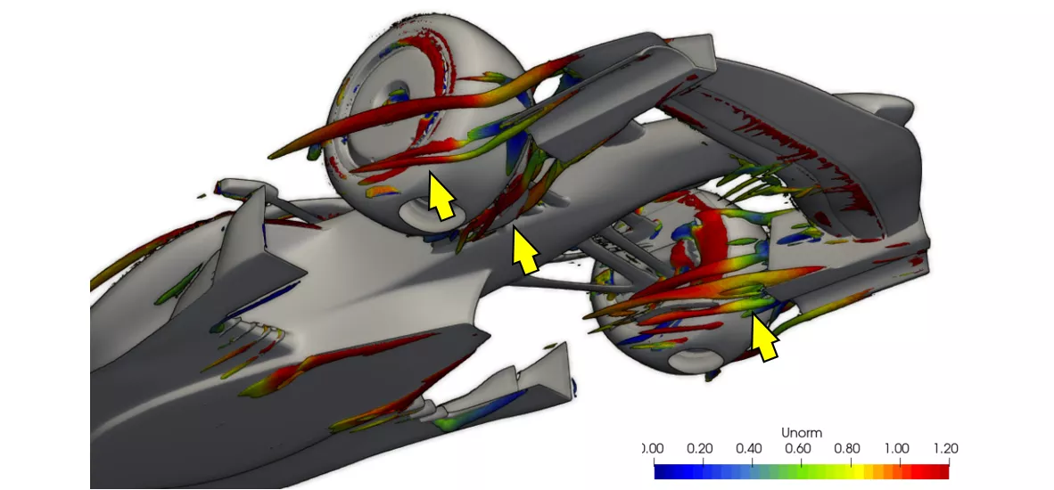
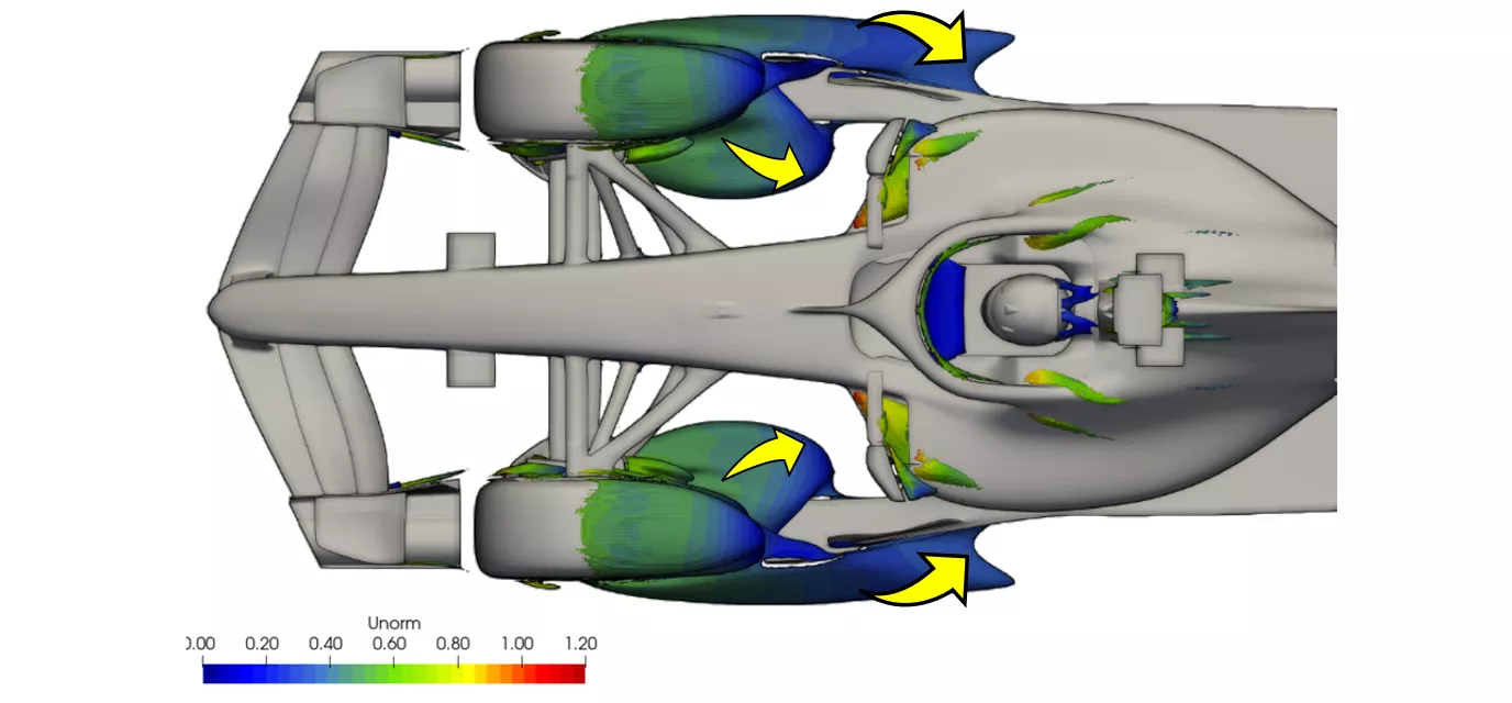
CFD image of the 2026 F1 car showing vortices being shed from the front wing endplates towards the front tyres

Aston Martin in windtunnel

Car, Innovation

Motorsport aerodynamics explained: the role of wings, stalling and diffusers

The image above shows the complex system of vortices that are being shed from the front wing endplates. Vortices, swirling structures of air which propagate downstream, form across the various edges of the endplate as the pressure difference across the wing seeks to equalise. 
As shown, these vortices interact with the tyre shoulder and contact patch which, when managed appropriately, can help reduce the losses generated by the tyre squirt; a jet of air generated between the ground plane and tyre patch.

The challenge is to try to ensure these mechanisms remain as stable as possible as the onset conditions of the airflow changes. 


As a driver begins to navigate a corner and apply steering, yaw angle and roll build, and ride height increases as aerodynamic load tapers off with speed. All of these changes run the risk of breaking down these well-optimised vortex interactions with the knock-on effect of undesired load and balance changes.

Front suspension fairings continue to be governed by reasonably strict rules, with only symmetrical profiles of maximum size and aspect ratio permitted. The opportunity to downwash (deflect airflow downwards) ahead of the floor is reduced by prescribing nose-down angles only. 
CFD analysis of the 2026 F1 car

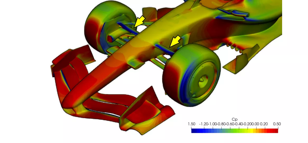
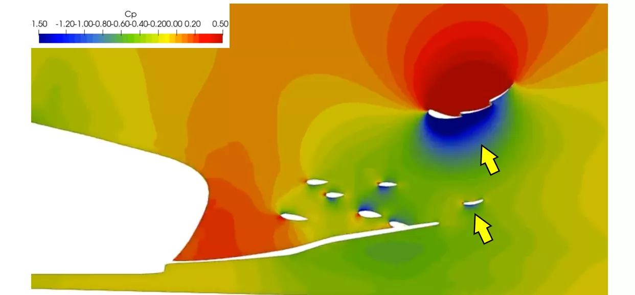
3D render showing pressure coefficient at the front of the 2026 F1 car model with the front suspension fairings annotated. This area is governed strictly in the 2026 regulations

Innovation

Pullrod and pushrod explained - and which F1 team is running which set-up in 2025?

This flexibility does at least allow for alignment of the suspension member (pointed to in the above image) to the flow presented by the front wing. The suction peak - the area of lowest pressure flow - is highlighted in blue above, being a consequence of the upwashing flow. 
 
Keep an eye out for teams making use of “local minimal exceptions” - areas where there are small allowances in area and size forced by necessity - around junctions to try and eke out every last bit of performance from this area.
 

The F1 2026 challenges posed by inward wake 

The initial set-up of flow on the 2026 F1 car is now clearer, but a look at the front tyres tells us more about how front tyre wake forms and interacts with the car downstream. 
 
The image below shows how the lower wake expands behind the front wheel to engulf the outboard section of the forward floor; a far-from-ideal scenario.
CFD analysis of the 2026 F1 car

A look at wake generated by the front wheels offers a clue surrounding one of the biggest challenges teams will face in 2026 F1 car design

Render of Aston Martin AMR24 showing Venturi tunnels effect

Innovation

Formula 1 aerodynamics: What are Venturi tunnels and how does porpoising affect F1 cars?

Inboard of the wheels, the expansion of the tyre squirt and lower wake is illustrated, with the turbulent air growing into the path of the floor leading edge. This reduction in total pressure will reduce the ability to extract performance under the car. 


Controlling this expansion has long been, and will doubtless continue to be, a key objective when developing the front end of the car.

The inwashing wake control board prescribed by the new regulations is also seen in action here, with the outboard tyre wake being encouraged inboard towards the sidepods. 

Aerodynamicists will be seeking to mitigate this to improve the quality of air reaching the rear of the car.

Taking a slice through the sidepods to produce a contour of the total pressure in the airflow - a firm favourite for aerodynamicists to visualise wake structures - shows that wake in this particular simulation is particularly bottom-heavy.
2026 F1 car CFD analysis

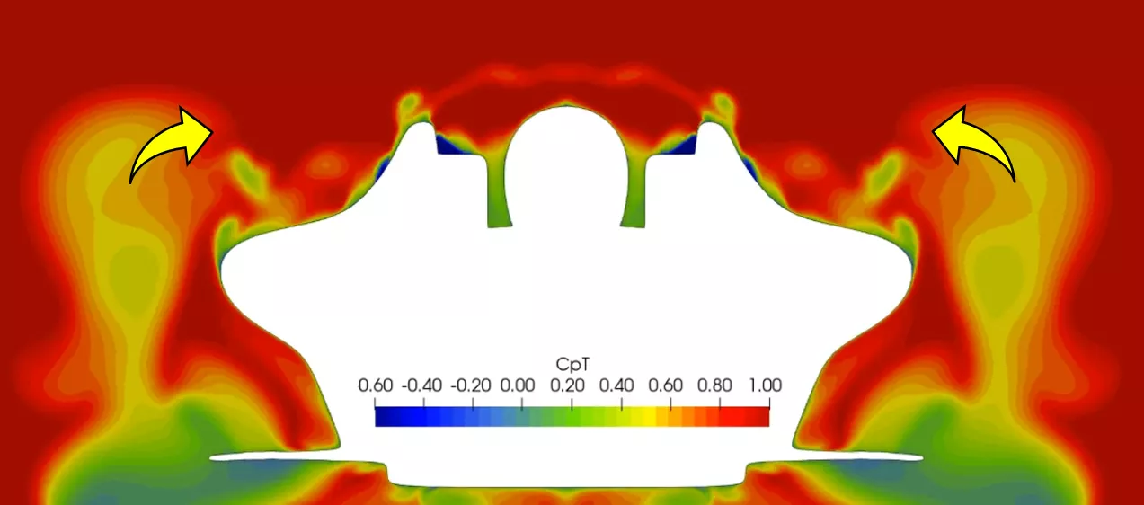
A look at the sidepods (with the driver’s helmet rendered as part of the simulation) shows where the bulk of front wheel wake will be fed

Airflow under an F1 car

Car, Innovation

CFD in F1: How does Computational Fluid Dynamics drive performance?

As wake feeds downstream, its upper lobe (denoted by arrows in the above image) tends to rotate inboard towards the sidepods and down to the rear quarter of the car. 
 
This is one reason why the current breed (from 2022 to 2025) of F1 cars capitalised on channels or gulleys to feed the higher energy air to the rear, with the high shoulders keeping the upper wake at bay.
 
Wake topologies can vary significantly depending on the onset flow to the front wheels and the front wing interactions, as described previously. 
 
The challenge is to find the right balance between the upper and lower wake, which offers the best total pressure field being fed to the rest of the car.
 

The F1 2026 diffuser problem 

At the rear of an F1 car, the objectives are to expand the airflow passing underneath the floor through the diffuser and to generate rear downforce to help provide balance to the aerodynamic load.
CFD analysis of the 2026 F1 car

Cross section CFD analysis of the 2026 F1 car's diffuser

Taking a slice through the diffuser and rear wing of the 2026 F1 car, the strong level of suction generated by the rear wing is highlighted by the blue static pressure region in the image above. 

The beam wing underneath (denoted by arrows) also acts to generate a smaller region of local suction. The circulation and lower pressure being driven by these components helps to reduce the adverse pressure gradient seen across the expansion of the diffuser.
CFD analysis of the 2026 F1 car

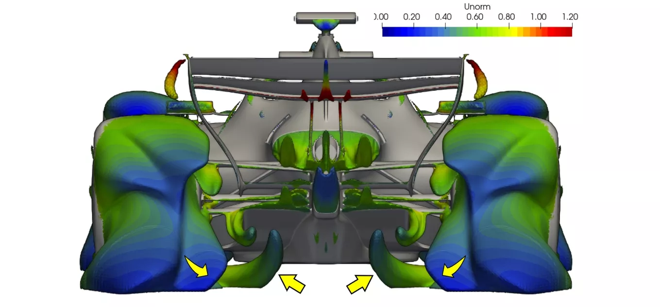
Render showing how rear tyre squirt (airflow deflected off the wheels) is deflected into the path of the diffuser of the 2026 F1 car - another area that designers and engineers will be keen to mitigate

Line of F1 cars in the pitlane

Car, Innovation

F1 upgrades: How are aerodynamic upgrades planned and deployed?


In much the same way as the front wheels, controlling the rear tyre squirt is critical to maximising the performance of the diffuser. 

As shown above, the losses jet into the diffuser and contribute to blockage, reducing the overall efficiency. The wake is also pulled across the exit of the diffuser, exacerbating this situation. 

The focus for aerodynamicists working in this region will be to utilise flow structures from the floor and rear wheel bodywork to mitigate these effects. 

Optimisation of the diffuser must be treated with care and across a variety of conditions. As the car accelerates and sees an increase in aerodynamic load, the ride height decreases, forcing the diffuser lower to the ground. 


In the extreme case, this can lead to the diffuser stalling and a consequent dramatic loss in overall downforce. To make matters worse, any lag in the system may delay the recovery of the diffuser as the car ride height increases once again.

2026 F1 diffuser area

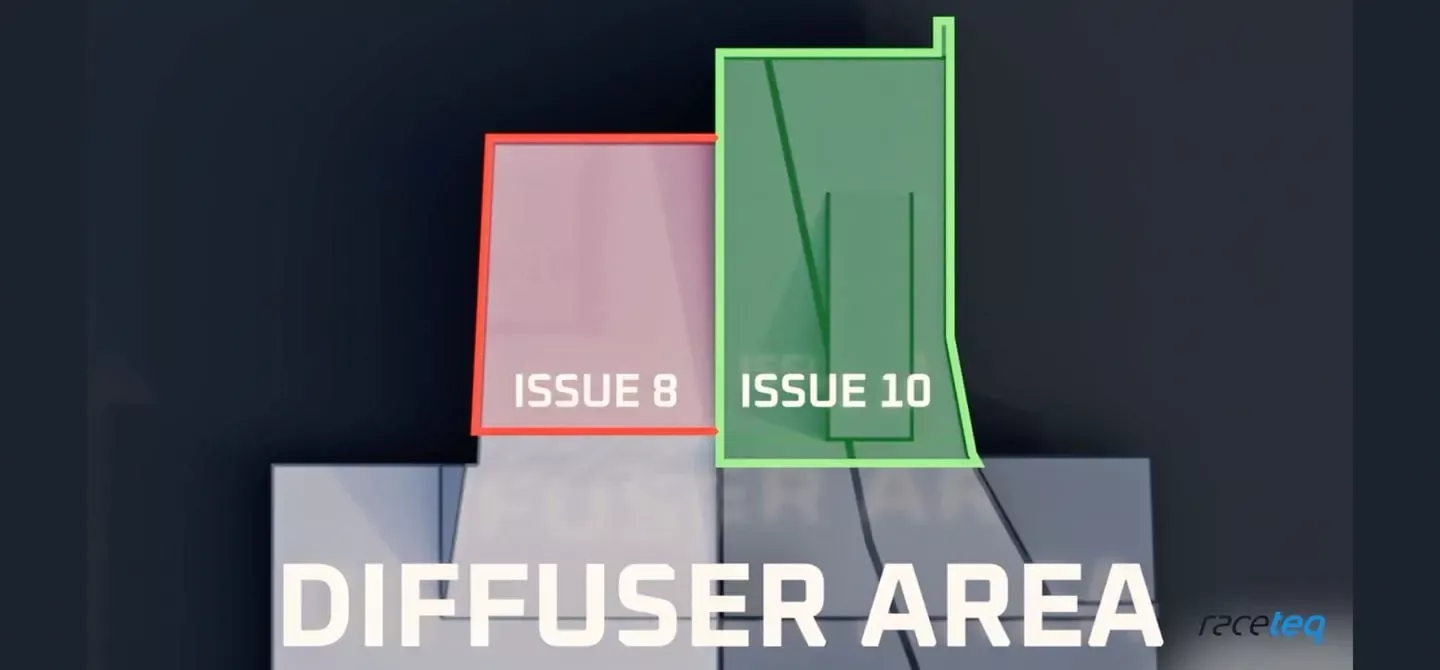
Diffuser area was increased in the latest (as of June 2025) 2026 F1 technical regulations - possibly to mitigate the loss caused by rear wheel tyre squirt

Is this a complete picture of the 2026 F1 car? 

The FIA’s clampdown on outwash airflow is nothing new as the governing body seeks to make overtaking easier and diminish the effects of turbulence, but the 2026 F1 regulations double down on this approach. 
 
Intricate flow mechanisms and interactions will be leaned on by aerodynamicists in the pursuit of performance in 2026, but engineers will also have to consider how active aerodynamics affect downstream airflow with the front wing now also part of this equation.
 
CFD is an incredibly powerful tool - with Bramble CFD’s help crucial to our early analysis of the 2026 F1 car - for visualising airflow and gaining a deeper understanding of the complex interactions taking place. 
 
This simulation is not however without its pitfalls and the model used is only representative of the shape of the 2026 F1 cars given the technical regulations available at this time. 
 
Only with windtunnel and real-life track testing will a more complete picture of airflow across the 2026 F1 car form - and even then, there’s no guarantee that every team will hit the ground running in the new era of F1.

Related articles

F1 car coke bottle profile

Car, Innovation

Why is the Coke bottle shape so important in Formula 1 aerodynamics?

McLaren F1 car 2025

Car, Innovation, Motor, Event

How Formula 1 teams set their cars up for the Monaco Grand Prix

Sign up to receive regular newsletters and ensure you stay ahead with exclusive articles on technological innovations and valuable insights into the world of motorsport

Make sure you're fully up-to-date in the world of race technology

By signing up, I acknowledge that I have read and understood the content of the RaceTeq Terms & Conditions

Motorsport technology uncovered. Features, news and interviews on the latest innovations in Formula 1, Formula 2, Formula 3, Le Mans, Dakar, and more.


  • Privacy Policy
  • Terms & Conditions
  • All Content © Raceteq 2025
  • All Rights Reserved