Car
F1’s longest circuit revealed how each team is upgrading its car for 2026
by Matthew Somerfield
10min read
Formula 1’s never-ending development cycle saw numerous teams arrive at the British and Belgian Grands Prix with update packages - and it was at Silverstone and Spa-Francorchamps where we saw the reality of each team’s development plan.
Sign up for a newsletter and we'll make sure you're fully up-to-date in the world of race technology
The sprint race format usually dissuades teams from making significant changes to their cars, owing to only having one free practice session to evaluate the new parts.
However, there were a number of teams that made changes at Silverstone, as they looked to make up ground on their rivals.
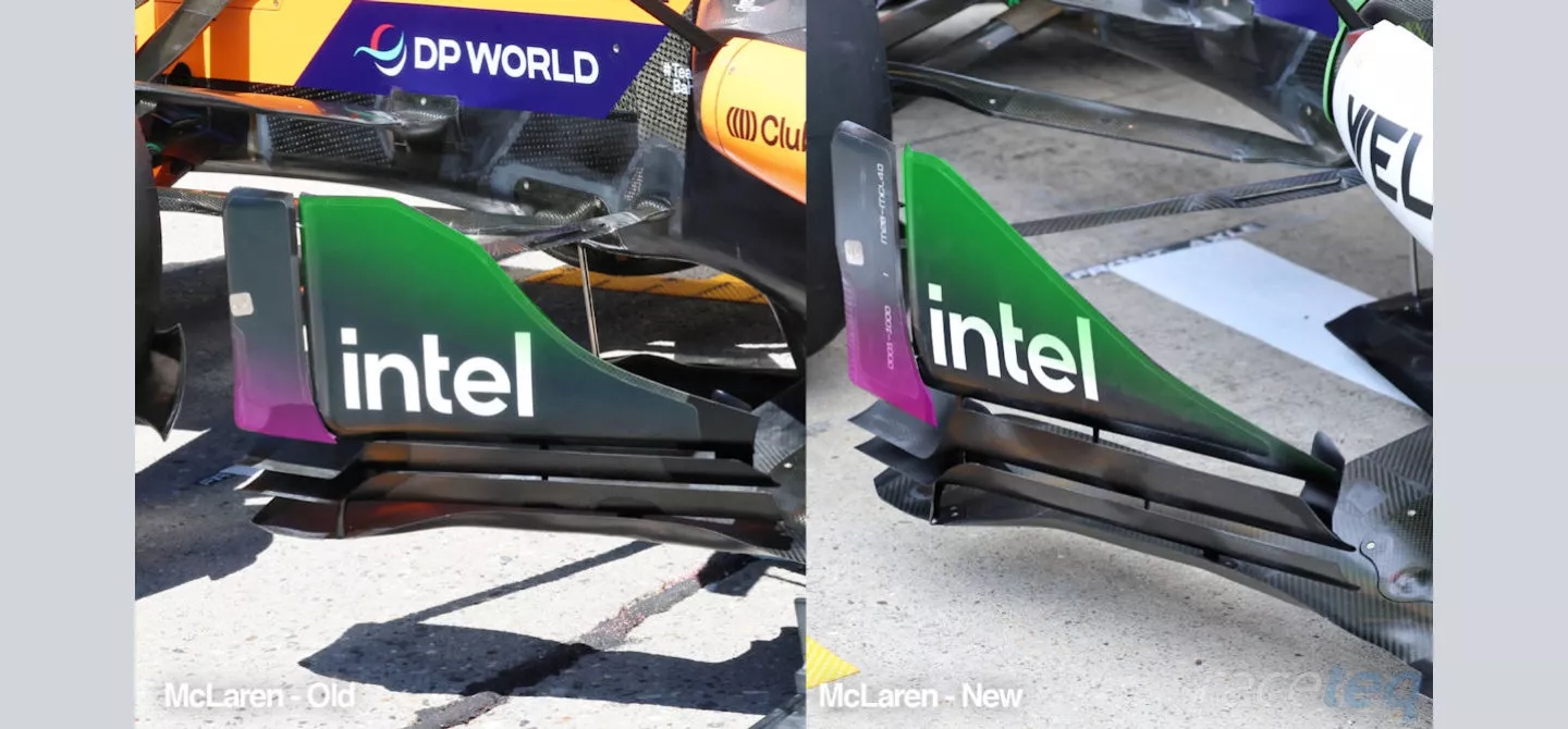
A comparison of McLaren’s floorboard region
McLaren: focus on the floor intensifies
McLaren’s new updates centered around the forward portion of its floor, with the design of its floorboard altered once more.
The lower curl on the forward skyscraper element has been revised (highlighted in purple), whilst the shape of the sail-like element has also been modified (green highlight).
As is the case with the design of these components it becomes a trade-off between what’s being achieved aerodynamically in the forward section, where there’s more freedom to angle the elements and the rear elements which must be angled inward.
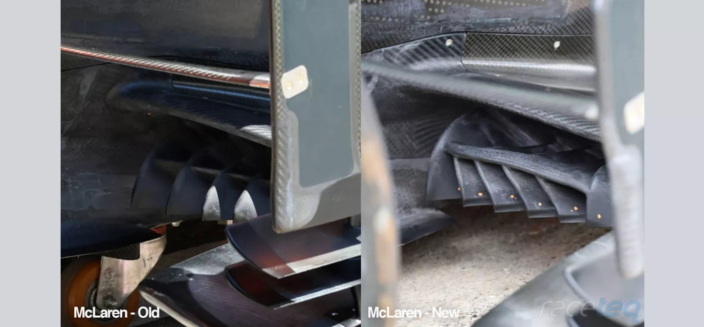
A comparison of the floor’s leading edge and fence design on the McLaren MCL40
McLaren is also looking to make strides with the design of the floor’s leading edge and the fences that can be connected to it.
In their previous guise (left), the fences were split by a horizontal blade, resulting in their leading edge being visible above and below the blade.
However, the new design (right) follows a similar design trajectory to the one we’ve already seen Ferrari take this season, where the horizontal element acts more like a slat, above the fence arrangement, as it no longer reaches up to the leading edge of the floor.
The geometry of the fences has changed too, now leaning away from the slats’ leading edge, rather than being rounded as in the previous configuration.
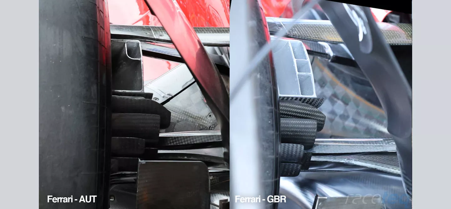
A comparison of the rear brake duct outlet and supplementary winglets beneath on the Ferrari SF-26
Ferrari: in with the new and the old
Ferrari made changes to its rear brake duct at the British Grand Prix, increasing both the size of the inlet and outlet, to help better manage brake temperatures and aerodynamic throughput.
In the comparison we
can see that whilst the outlet appears to be similar in size, there’s
clearly more going on in terms of the divisible ductwork that lines
the outlet.
Meanwhile, the size and shape of the winglets stacked beneath the outlet were also altered to take advantage of the aforementioned alterations and leverage their revised behaviour.
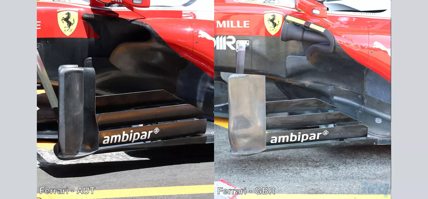
Comparison of the different floorboard arrangements raced by Ferrari in Austria and Great Britain
Ferrari also reverted to an older design concept when it came to its floorboards at the British Grand Prix, as it switched from the triple element arrangement (used since Miami) for one more conceptually aligned with the early season arrangement, and for which the team tested in Austria.
This is understood to be a lower downforce offering, with Silverstone and Spa sat within that envelope, rather than being an overall design successor, as the triple element returned at the Hungarian Grand Prix.
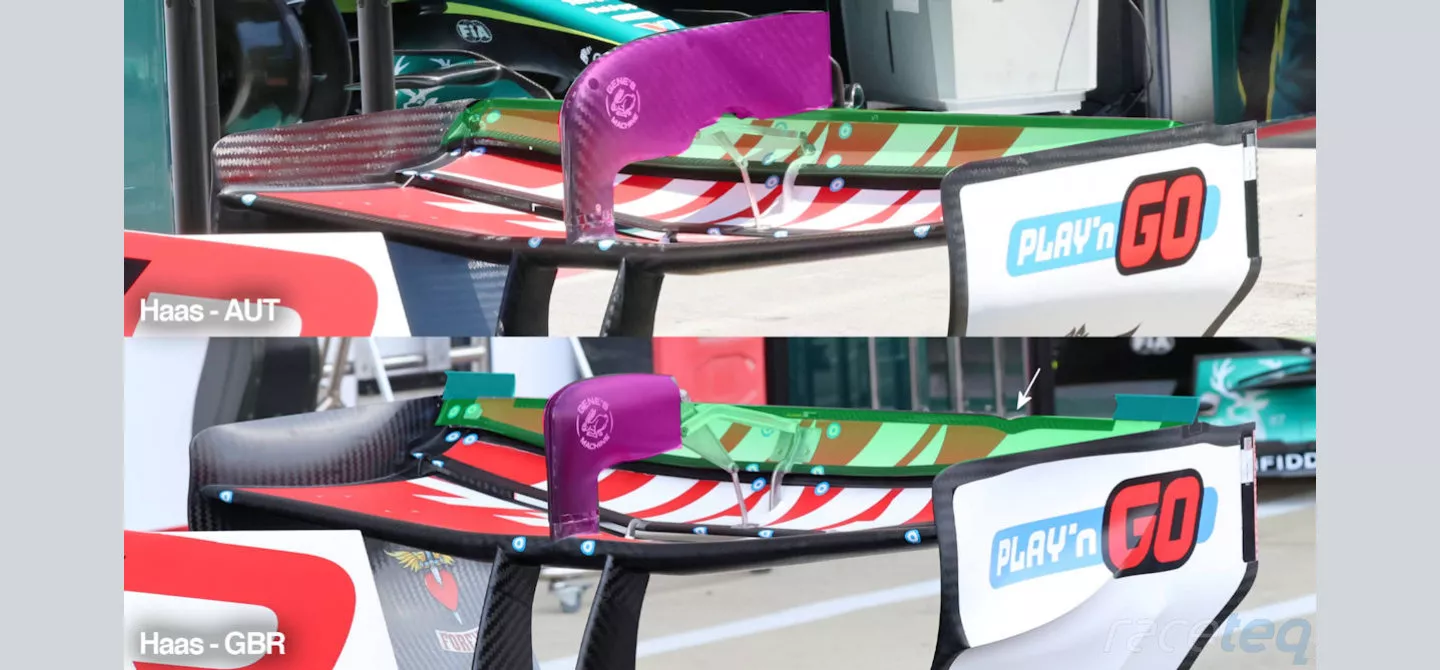
Comparison of the different rear wing specifications used by Haas in Austria and Great Britain
Haas’s design DNA becomes clear
Haas introduced a new rear wing arrangement at the British Grand Prix, that not only adopted features seen elsewhere, up and down the grid, but also something that’s a callback to a design solution we saw a few regulation sets ago.
Redesigning the front and rear wing of this year’s challengers has been a different prospect for the teams, as there’s no longer a real need to build what we’d ordinarily consider low, medium and high downforce packages.
Of course, there’s still some limited changes being made in that respect to help balance the cars on a circuit-by-circuit basis but the use of active aero largely negates this, as they’ll more or less take as much downforce as they can have for the corners, whilst that’s dumped on the straights when the wing angle is altered.
The changes made by Haas look to balance these two states too, leveraging the additional downforce that might be on offer, against the backdrop of how much drag can be shed when active aero is in operation.
Added to the outermost corner of the upper flap are deemed as ‘rotation brackets’ to fall within the confines of the regulations but are often termed as ‘hanger flaps’ by the teams (light blue highlight)
These surfaces have been fashioned to create an extension to the flap below and even incorporate its own Gurney flap.
The ‘hanger flaps’ employed by Haas have been split into two sections too, with the outermost section remaining static, whilst the inner section rotates with the upper element when active aero is deployed.
This is a solution that we’ve already seen widely adopted by its rivals, with Mercedes the first to implement such a design and for whom we’ve already seen additional design changes made.
Alongside those new hanger flaps is a feature we saw designers employ in the pre-ground effect era, with smaller V-shaped notches taken out of the elements' trailing edge (white arrow).
In response to these changes, the chord length of the mainplane and both movable elements were also altered, with a more swept design employed on all three, resulting in a deeper mainplane in the outer section, whilst both upper elements had their chord height reduced.
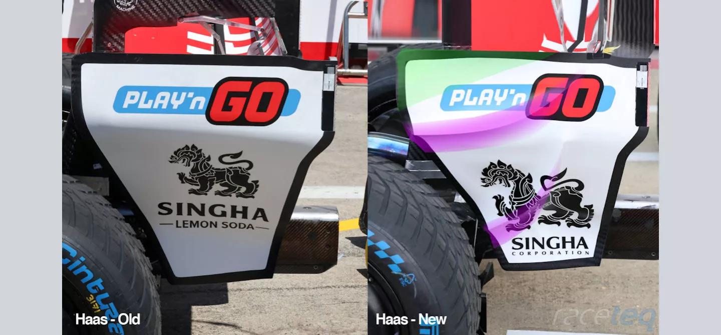
Comparing the new and old rear wing endplate design on the Haas VF-26

The VF-26’s rear wing endplate was also revised quite heavily at the British Grand Prix, as the team seemingly took inspiration from its rivals, who have been implementing similar designs this season.
However, it’s not the first time we’re seeing these employed, with Aston Martin and Alpine simultaneously adopting their own versions of them at the Monaco Grand Prix in 2023.
The addition of these swage lines on the endplate not only add some limited local downforce of their own, they help to tidy up some of the turbulence from the rear tyre that might otherwise have an impact on the performance of the diffuser and rear wing.
This is important when we consider the lateral expansion of both of these downforce generating components and the vortical structures that are produced at their edges, both of which should be more stable owing to the reduction in turbulence.
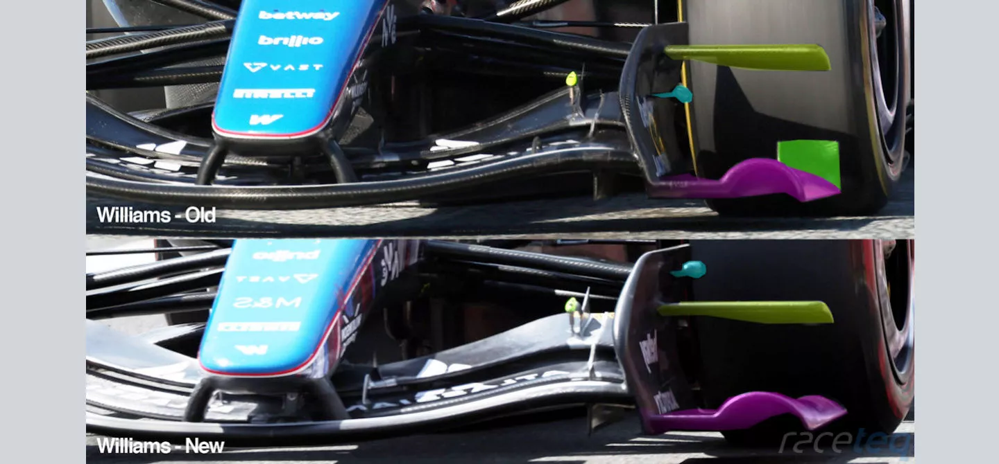
A comparison showing the different detail between the two specifications of front wings from Williams
Williams serves up new front wing solution
Williams arrived at Silverstone with a revised front wing design that the team hoped would help turn its fortunes around.
The changes are in a
similar vein to those we’ve seen others make beforehand, with the
components on the outer perimeter all reconfigured to better serve
how they want to generate outwash.
The curled section of footplate (highlighted in purple) has been overhauled in numerous ways, with a flatter curvature employed, whilst the leading edge is angled back away (see side comparison, below).
And, given the alterations to the curled section have resulted in a more gradual slope to the rear, the outwash vane that had previously been situated at the rear of the surface has now been deleted too.
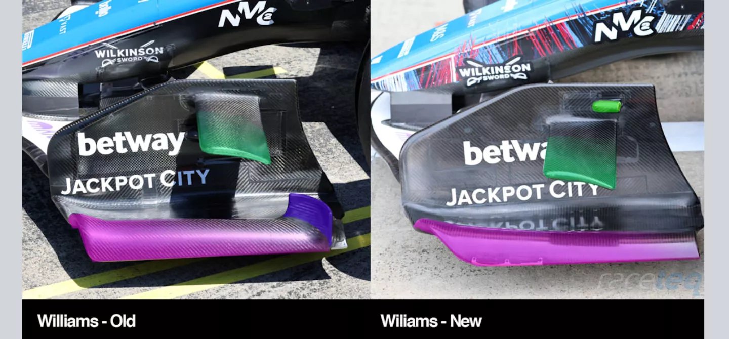
Comparing the different footplate, diveplane and other aerodynamic features in this region on the Williams FW47
Notably the diveplane and infra-red tyre sensor pod have switched positions too (green highlights), with the pod now positioned above the diveplane, rather than below.
The diveplane remains reasonably similar from a design perspective but the lower position it now sits on the endplate has resulted in the angle at which it’s mounted being altered.
The two-week gap between races and a very different circuit configuration for it to consider led to further updates being introduced by the teams at the Belgian Grand Prix.
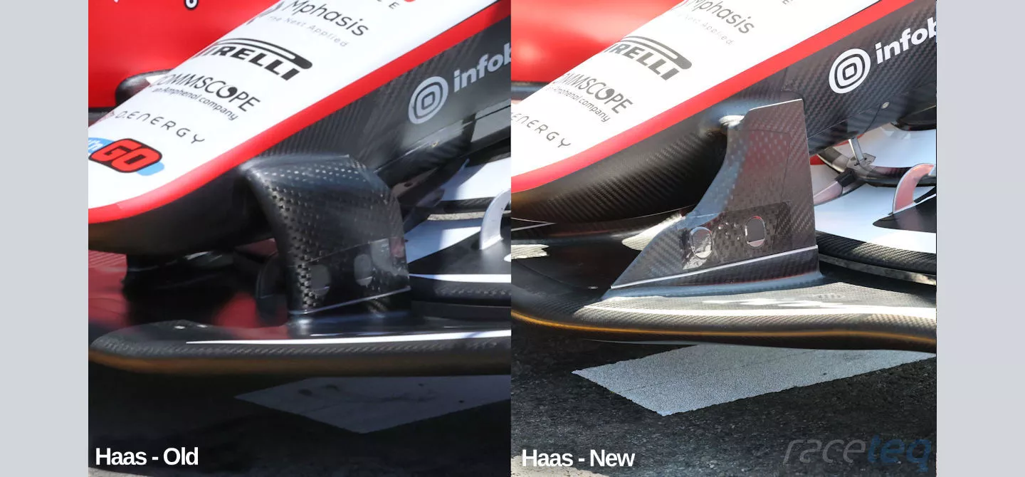
A comparison of the new front wing pillar arrangement that Haas introduced in Belgium (right) and its previous specification (left)
Haas introduce innovative new solutions
If there was an award
for the most interesting design solution of the season, this new
front wing pillar design from Haas would certainly rank highly and is
sure to have its competitors looking at implementing it for
themselves too.
The previous pillar design (left) served the purpose of supporting the front wing perfectly well, whilst offering some aerodynamic support, albeit more from a neutrality point of view.
Meanwhile, the new design is serving much more of an aerodynamic function, whilst still fulfilling the support criteria.
Notably the J-shaped pillar arrangement has a much greater sense of aerodynamic presence, with the edges expected to propagate useful vortices that can support the downstream flow structures.
This is aided by the pillars being displaced from the nosecone, with a spar connecting the nose and wing pillars, which creates surface discontinuity at the top of the pillar element to further aid in their aerodynamic endeavours.
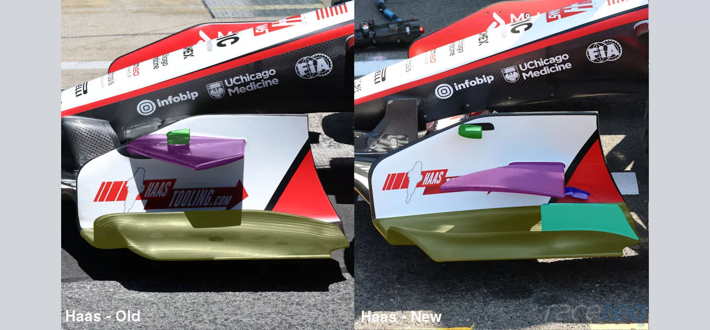
A comparison of the new front wing footplate, diveplane and vane arrangement used on the Haas VF-26 in Belgium (right), with its previous design (left)
The remainder of the front wing was completely overhauled too, with significant changes made to the layout of the footplate, guide vane, diveplane and infra-red tyre monitoring camera pod.
The previous footplate design was unique to Haas, with a more squared arch in the outer section that was set back from the leading edge and also formed an elongated vane along its length (yellow highlight).
The footplate now resembles the design seen elsewhere on the grid, with a more subtle arch and a large vane in the rear corner (light blue highlight).
The diveplane’s position has not only been altered, having previously been attached on the leading edge of the endplate (highlighted in purple), its leading edge is now swept in the opposite direction.
The pod that encloses the infra-red tyre monitoring camera had previously sat atop the diveplane (highlighted in green) but now sits alone, mounted in a similar position, albeit from the side of the endplate.
Two additional winglets can also be found hung from the side of the endplate below the diveplane (highlighted in dark blue) and will further engage with the airflow passing by that region.
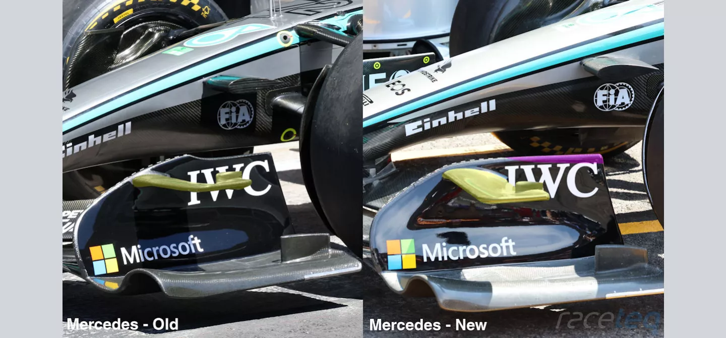
Comparison of the new front wing specification that Mercedes used in Belgium and the one prior
Mercedes builds on its success
Mercedes arrived at the Belgian Grand Prix with a revised front wing and new rear wing for the W17, as it looked to cater for challenges that the circuit layout holds.
The modifications to
the front wing included deleting the cutout in the upper corner of
the endplate (purple highlight), owing to the ratio of the endplate’s
upper edge and curved forward section also being modified (white
dotted line).
This also facilitated a change to the chord length of the diveplane where it attaches to the endplate, all of which will have an impact on the downforce being generated and their role in generating outwash.
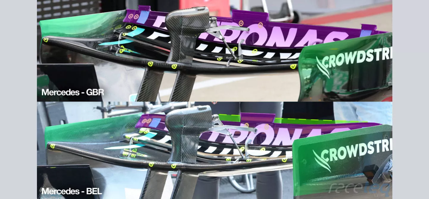
A comparison of the two rear wing specifications that Mercedes had at its disposal in Belgium

A lower downforce rear wing variant was also introduced in Belgium, albeit being abandoned during the course of the weekend and their previous specification raced.
The new design overhauled a number of the wing’s design aspects including the endplates (highlighted in green), which were returned to a more conventional flat layout, rather than possessing the curvature of the earlier specification.
Given that the curved variant possesses characteristics aligned with improving the amount of downforce that can be generated, whilst also affecting tip vorticity, it’s unsurprising that a lower downforce variant was paired with changes to the flap configuration.
In that respect, the most obvious difference between the two specifications is the shape change that’s been made to the trailing edge of the upper flap (highlighted in purple), with a curved profile employed that reduces the chord length across its span but primarily in the central section (dotted line).
These geometry changes extend to the outboard sections of the wing too, where a taller upper flap resulted in the secondary flap’s chord length also being altered (white arrows).
Meanwhile, the ‘hanger flaps’ mounted in the corners of the upper flap have also been discarded.
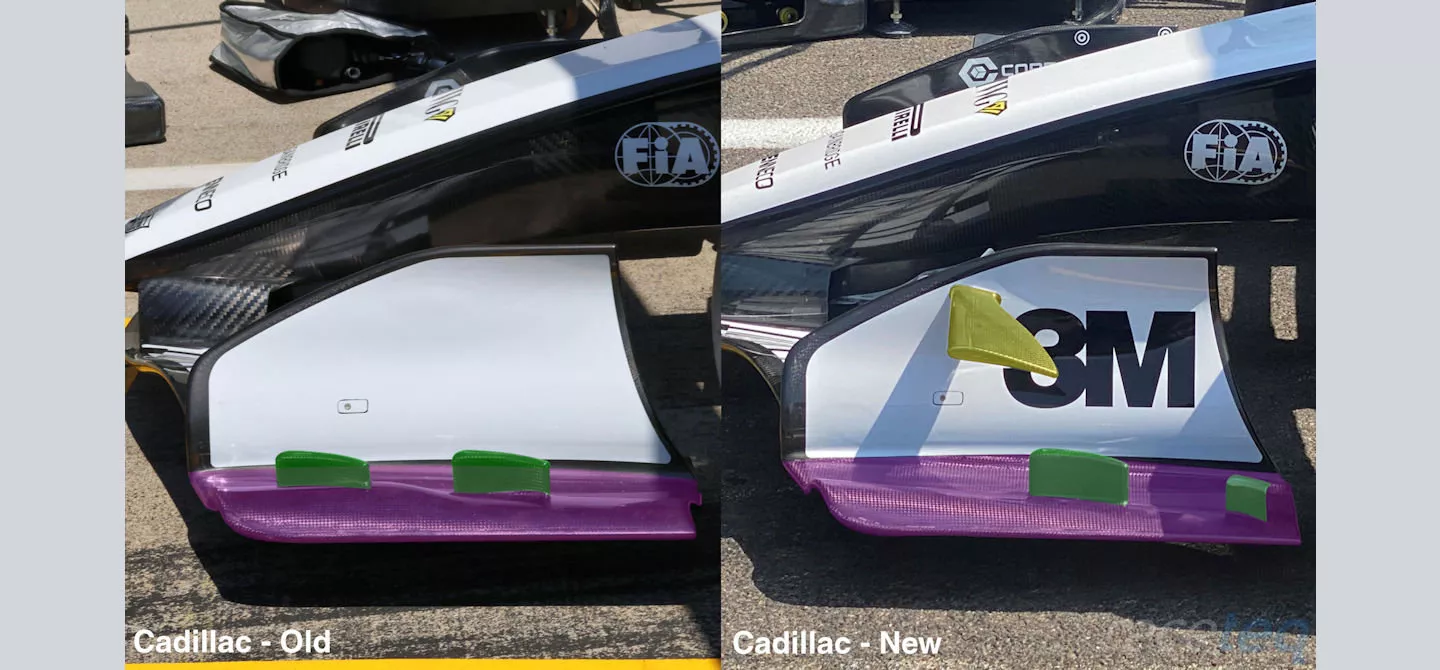
A comparison showing the difference in detail between the new Cadillac front wing (right)and the one used up until the Belgian Grand Prix (left)
Cadillac revisits old ideas
Cadillac made some
extensive changes to the outboard portion of its front wing at the
Belgian Grand Prix, with alterations made to the footplate
(highlighted in purple) that reduces the size of the arched tunnel
section, due to a more gradual taper being applied along its length.
This has been paired with a change in the position of the two vanes mounted on top of that section (highlighted in green), which now sit further back and are angled and shaped differently than they were before.
Meanwhile, having tested a solution during pre-season testing with a diveplane, the team has been able to incorporate one again with the aforementioned alterations (highlighted in yellow).
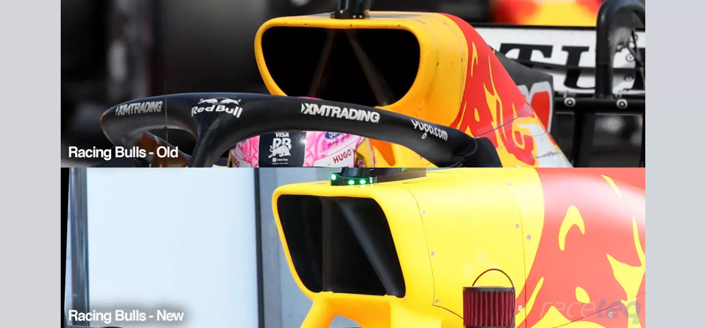
Comparison of the two different airbox and roll hoop designs seen on the Racing Bulls VCARB03 in Belgium
Racing Bulls tries to keep its cool
Racing Bulls has been relatively proactive with its implementation of updates throughout the course of this season, with the Japanese Grand Prix marking the only event that the team hasn’t had new components at its disposal.
At the Belgian Grand
Prix, it had a number of new components for the VCARB03
but only enough to install on one car, which led to an interesting
discussion between team principal, Alan Permane, and its two drivers
Liam Lawson and Arvid Lindblad.
“Honestly, we don't like bringing updates for just one car. It was impossible for us to do it to two cars [as] it's a chassis modification, we had to shrink the roll hoop,” Permane explained.
“I sat down with both drivers in Austria on Saturday evening. We had a very good qualifying. So OK, while everyone's in a good mood. I'll give some bad news: ‘We got a good update coming but we can only do one car for Spa, and the next car will be done for the race after in Budapest’.
“So I first suggested the very simple option that makes it fair is we upgrade no cars for Spa and then both of them for Budapest. Of course, they looked at me like I was crazy - and I wouldn't have ever done that [anyway]. We didn't really seriously consider that.
"The next thing we can do is flip a coin - or we can make it a little bit of fun and we'll say whoever qualifies in front in Silverstone gets the upgrade, and they both signed up for that. That's what we did.”
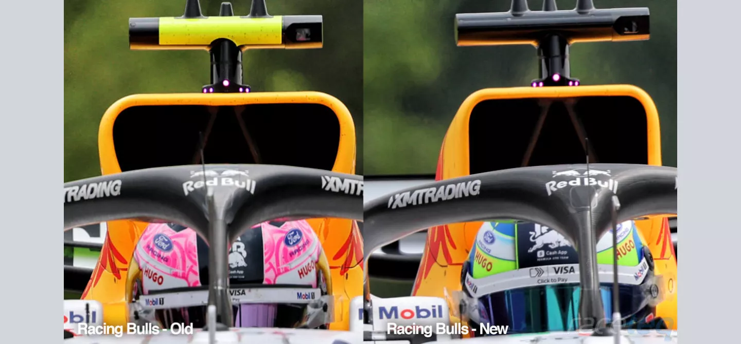
A comparison of the old airbox design on Lawson’s car, whilst the new arrangement was installed on Lindblad’s car.
The difference between the two airbox designs is obvious, with the extremely large inlet arrangement that’s been employed since the start of the season replaced with something a little more compact.
It’s still on the larger side of those being used this season but given the changes made to its sidepod bodywork, it would suggest it has been able to shrink the airbox by redistributing some of the ancillary components that need cooling, giving an aerodynamic boost to this region.
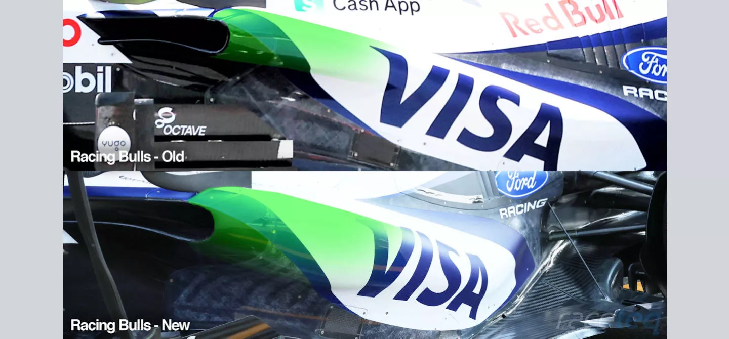
Comparison of the two different sidepod solutions on the VCARB03
The most obvious difference in the two sidepod solutions raced in Belgium is the size of the shoulder, with a more bulbous arrangement visible on Lindblad’s updated VCARB03.
This suggests the internal packaging has been amended, with the aerodynamic surfaces of the bodywork adjusted to accommodate it, without creating a substantial performance deficit.
This results in a more rounded shoulder section (highlighted in green) and some modifications to the undercut and G-Line - the line under the sidepod bodywork, starting from the undercut and working its way to the rear - with a bigger underbelly visible on the new solution.
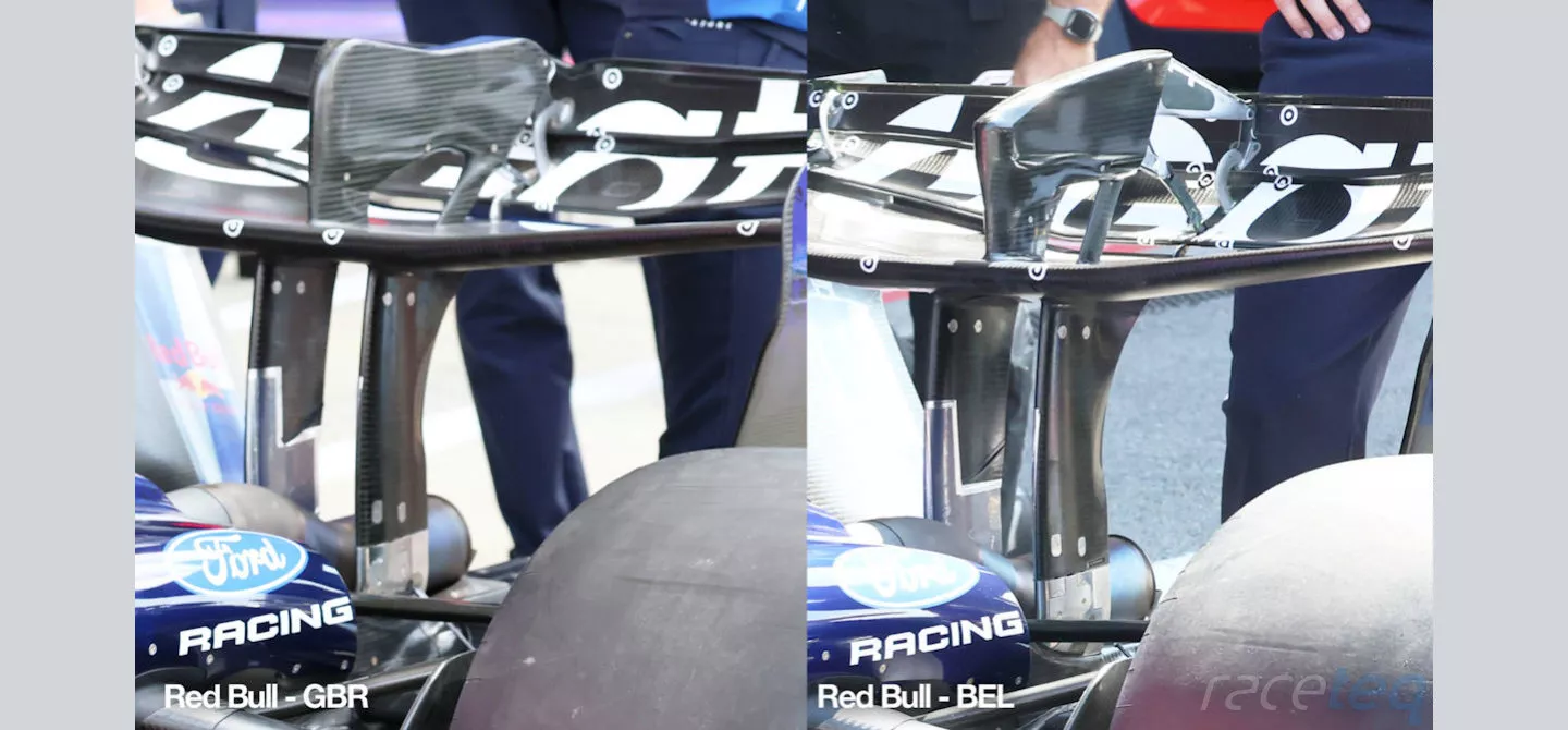
Red Bull’s rear wing solutions from the British and Belgian Grands Prix
Red Bull recognises its shortcomings
After a thorough review by the team following crashes involving Max Verstappen in Austria and Great Britain, Red Bull decided to park its inverted ‘macarena’ style rear wing solution (left, in the above image), returning to the more conventional active aero arrangement (right).
Acknowledging that it had issues with the design, the team have subsequently made changes, the root cause of which likely lies with the actuation mechanism, as described by technical director, Pierre Wache.
“It's a mechanical problem that we spotted after the accident in Silverstone,”
Falling short of giving specifics, it’s clear that the team is going to make sure it’s ready to go as soon as possible but won’t take further risks to do so.
“We don't want to take any risk, and we want to be 100% sure.”
“We are trying to prove that we are bulletproof before we put [it] on the car, and it should be ready for Budapest.”
/xpb_1408348_hires-(1).webp?cx=0.5&cy=0.5)