Car
Formula 1 technical analysis: How did teams upgrade their cars for the final Dutch Grand Prix?
by Matthew Somerfield
8min read
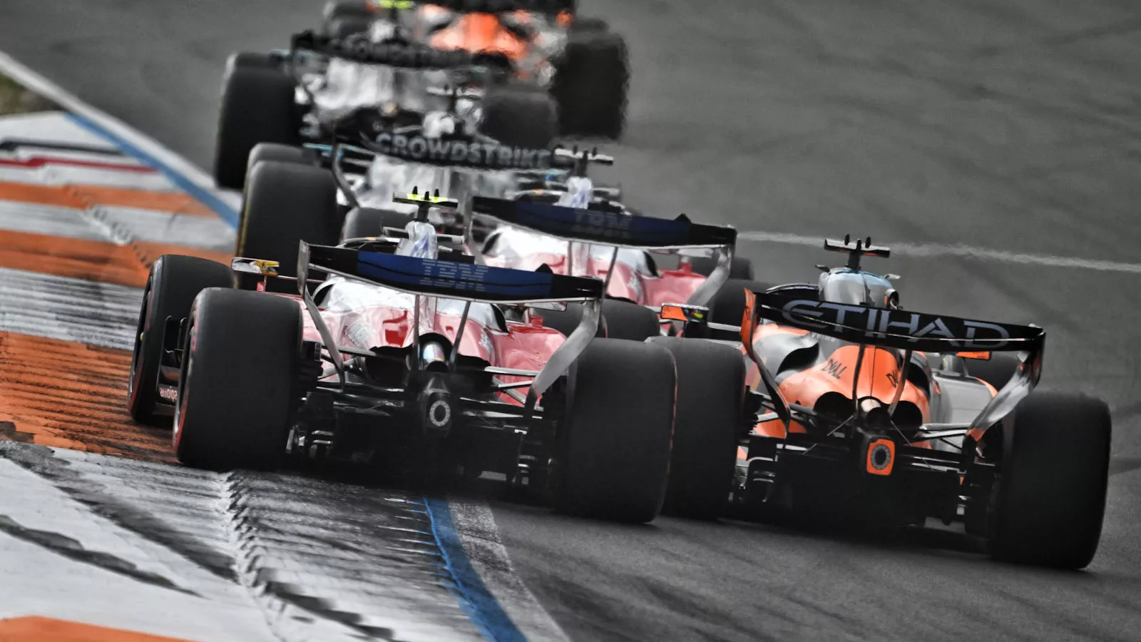
Formula 1 returned to Zandvoort for the first race after the summer break but the last for the Dutch venue as it leaves the F1 calendar for the foreseeable future.
The 2026 Dutch Grand Prix also provided the backdrop for another sprint race, resulting in just one practice session, which usually deters teams from bringing larger update packages. However, in a season where there’s still plenty of performance to be found, there was a generous offering on show, including a substantial update package for Alpine.
Alpine fast-tracked the production of the package for the Dutch Grand Prix and only had enough parts to install it on one of its cars, with Pierre Gasly the recipient, whilst Franco Colapinto was set to receive the upgrade in Italy.
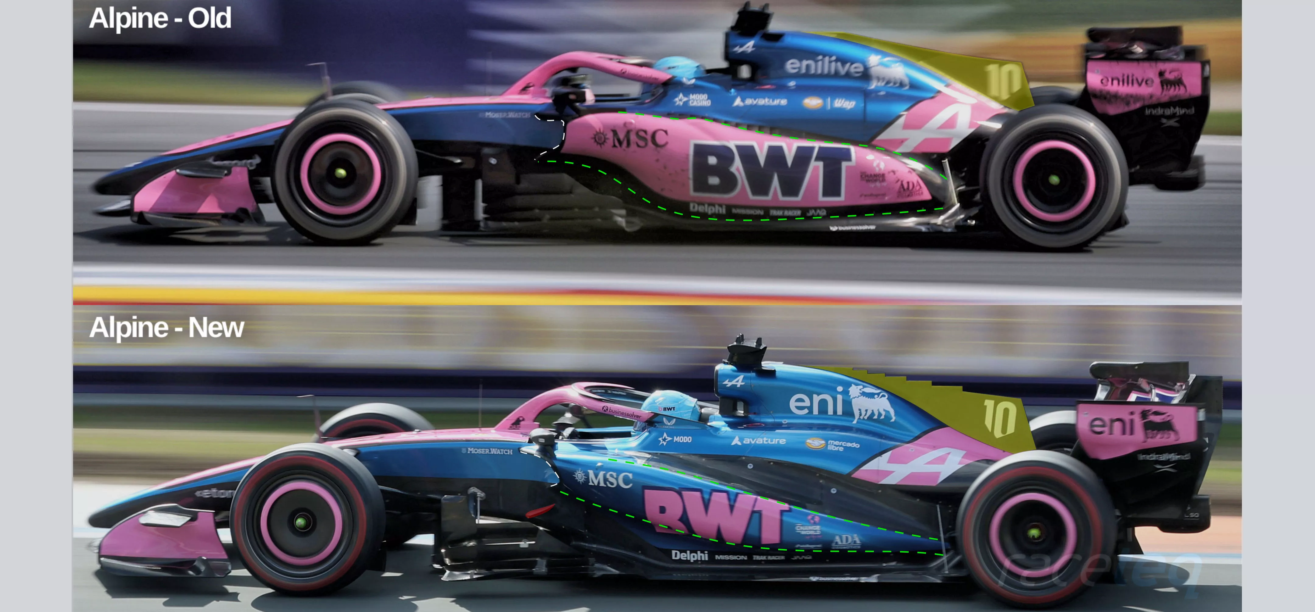
A side-by-side comparison of the two different bodywork specifications on the A526
Sign up for a newsletter and we'll make sure you're fully up-to-date in the world of race technology
It’s clear from the side-on comparison that the A526 has been completely overhauled by the update package, with a new floor, floorboard arrangement, sidepods and engine cover, whilst there’s also changes that have been made to the rear wing, diffuser and exhaust winglet layout.
There’s quite a stark contrast in the design of the sidepod bodywork with this redesign, as noted by the green dotted lines, which show how much the contours have changed, which results in a less bulky outline.
This is a consequence of the team both looking for aerodynamic performance, whilst also becoming more proficient with the Mercedes power unit, having opted to take supply from it rather than continue with its own power unit programme.
The much slimmer bodywork that now envelopes the internal components, such as the radiators, coolers and electronics, has a flatter, ramp-shaped upper surface that softly tapers to floor and Coke-bottle bodywork at the rear of the car.
Meanwhile, there’s a much more generous undercut at the front of the assembly, which continues to cut in tightly all the way to the rear, where it meets with the down-sloping upper surface of the sidepod.
Alpine has also joined the serrated engine cover ranks, with McLaren and Ferrari having started the season with a similar solution, whilst Cadillac joined the ranks in Austria.
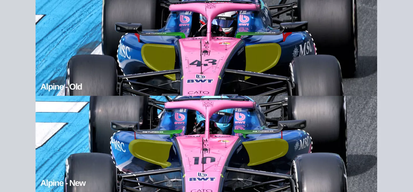
A comparison showing the new sidepod design and reconfigured mirror furniture on the Alpine A526
The sidepod inlet shape has also been adjusted as part of this update, with a now wider but shallower approach taken to its design (yellow highlights), which has created more room for the aforementioned undercut (dotted white line).
The designers also took the opportunity to revise their wing mirror layout, with the outboard supports being minimised, as they removed the vane that had previously performed its own aerodynamic function here (red highlight).
At the inboard end the team has opted for a continuation of the slat section to create a tip section, which will undoubtedly create a useful vortex to clean up any losses associated with the cockpit and halo.
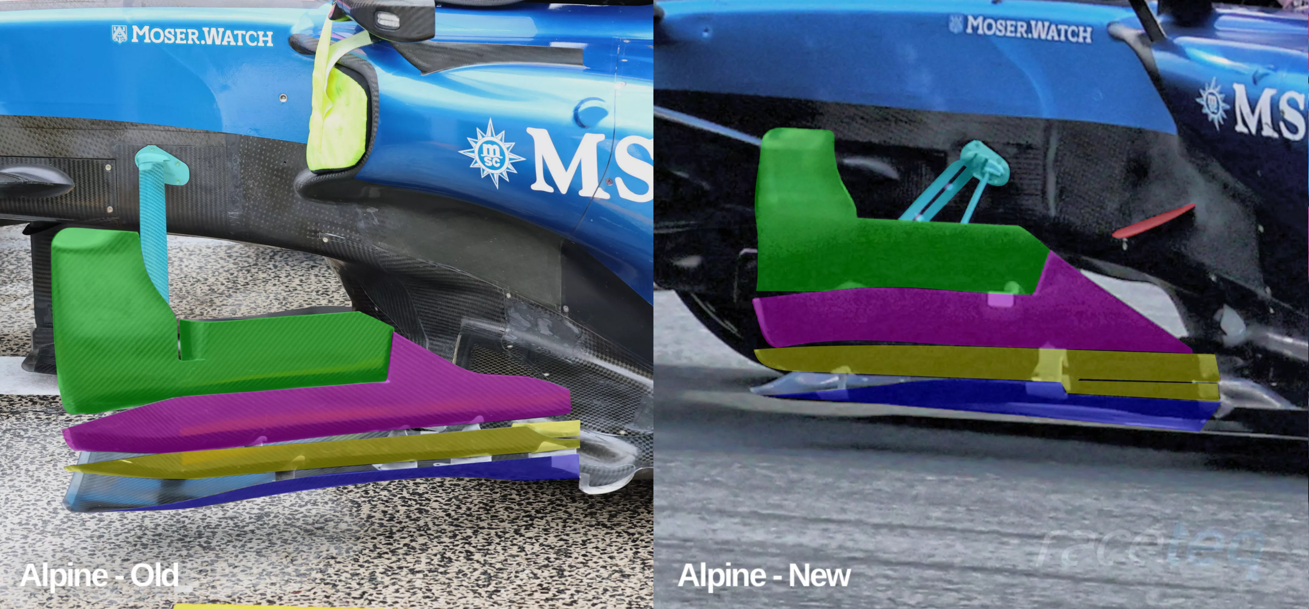
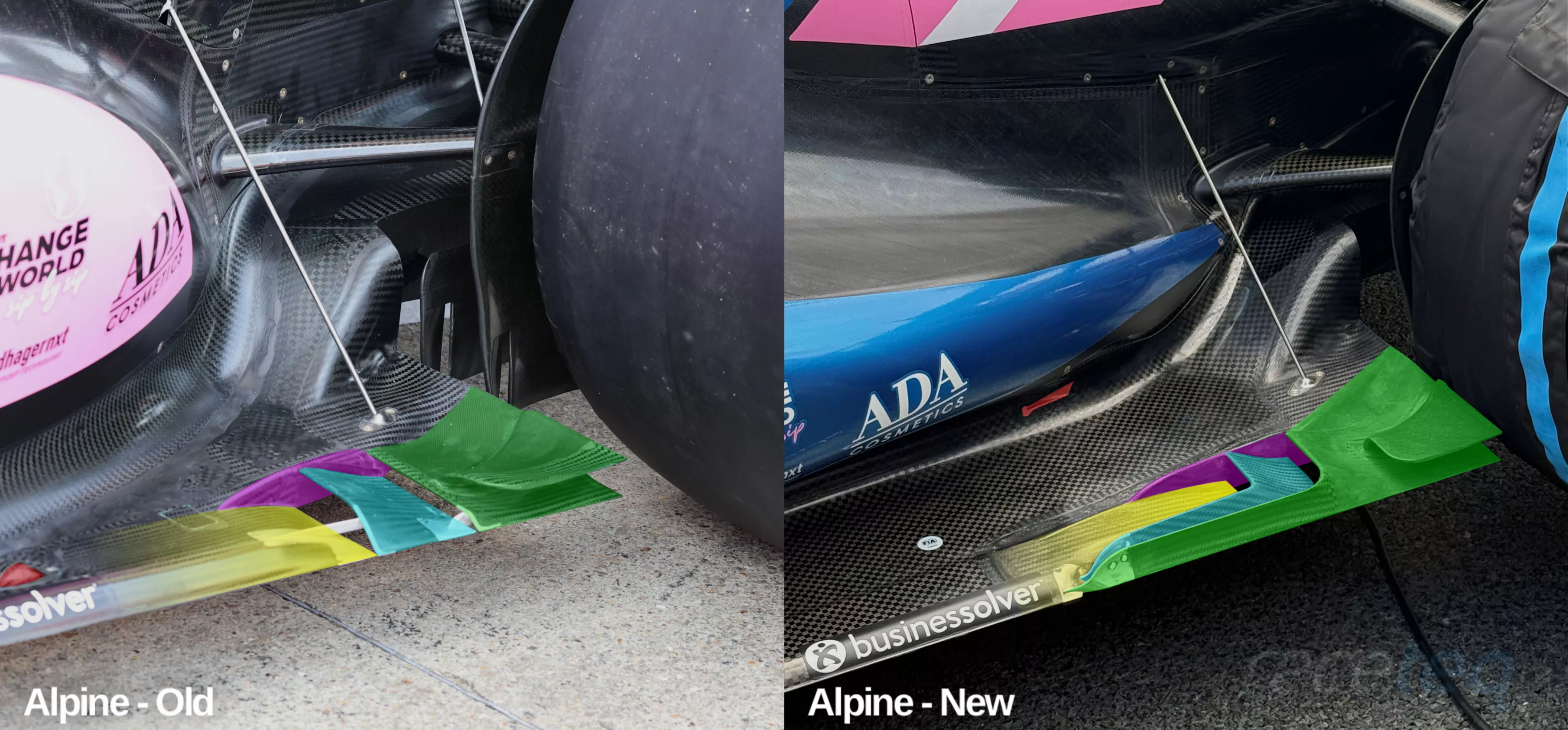
Comparison of the floorboard region on the Alpine A526
A close up of the floorboard arrangement on the A526 suggests that the team hasn’t completely walked away from the concept it’d already been using but it has made some tweaks to it.
The upper element has a similar layout to its forebear but the second element (highlighted in purple) has been adjusted, in order that the rear upper edge is a sharp line from top to bottom, rather than being tapered in the central section.
The double tail feature that the team had employed with the third element (highlighted in yellow), has also been extended, along with changes to the bracket system that holds this region in place.
The designers have also incorporated a slot within the main brace and added a metal support that connects the floorboard with the chassis (highlighted in cyan).
To help guide the flow around that front section of the sidepod, the team has also installed a diveplane on the chassis ahead (highlighted in red, above).
A comparison of the rear section of the floor on the Alpine A526
Alpine has also overhauled the rear section of its floor, as it looks to better combat the ill-effects of an aerodynamic effect known as tyre squirt, whereby turbulent jets of air are pushed laterally into the diffuser’s path as the tyre deforms and robs it of performance.
The new solution bears more of a resemblance to the one introduced by Mercedes in Japan and which some of its other rivals, including McLaren, have also assimilated.
Of course, there’s still some of Alpine’s design DNA embedded within, as it has retained the dog-eared flap design of its predecessor just ahead of the rear tyre (highlighted in green).
But, the section this sits upon has been extended forward to create an L-shaped profile along the floor’s edge.
The section ahead of that now also forms a similar L-shaped profile (highlighted in cyan), whilst the sidewall it’s mounted upon has also been extended (purple highlight).
This results in a narrower profile for the section ahead (yellow highlight) to make way for the L-shaped arrangement but extends the whole section forward as a consequence.
As an aside, the comparison also shows how the position of the sidepod bodywork has led to a narrower diffuser kick section on the upper surface of the floor.
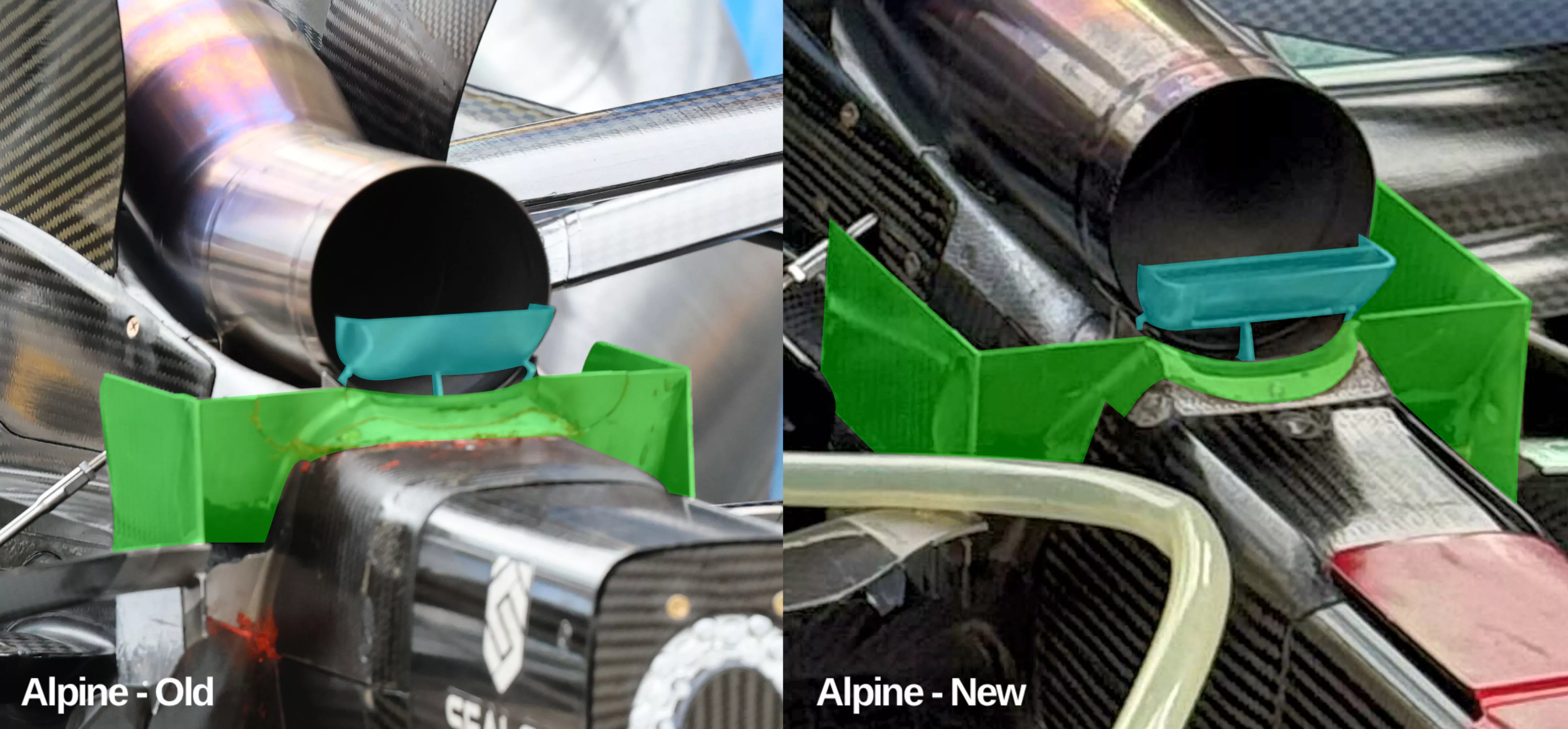
Comparison of the rear crash structure and exhaust bracket design on the Alpine A526
Alpine was one of the first in a clutch of teams to try and combat Ferrari’s flick-tail-mode (FTM) solution - where a small plane sits at the exhaust exit and directs gases upwards to enhance downforce - with a similar arrangement in Miami, albeit taking advantage of the exhaust bracket regulations, rather than the criteria used by Ferrari to create its arrangement.
It updated its offering at the Dutch Grand Prix, modifying not only the metal bracket itself (highlighted in cyan) to incorporate two additional slots but also the crash structure surround (highlighted in green), which sees the ramp section below the bracket altered to better facilitate how the exhaust plume behaves as it exits.
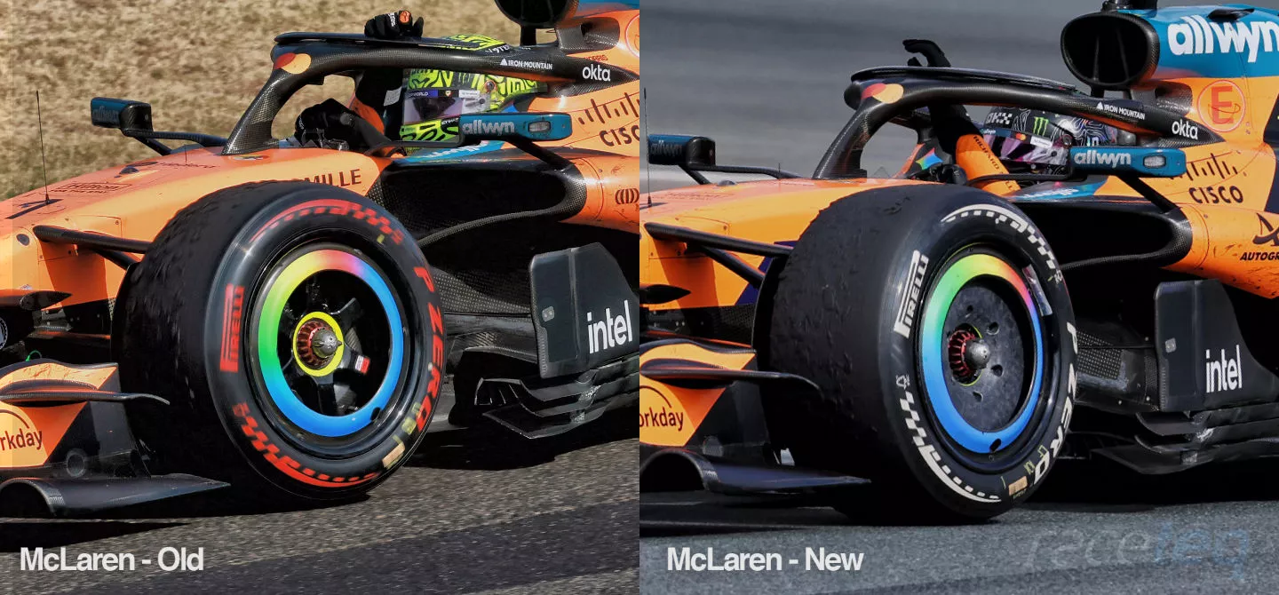
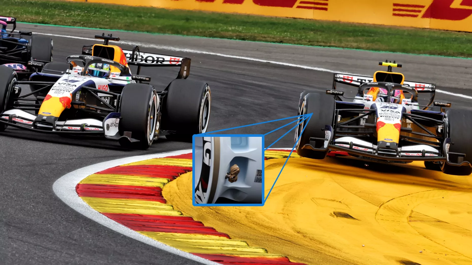
Comparing the new front wheel design raced on the McLaren MCL40 at Zandvoort with its predecessor
McLaren continues to push
McLaren arrived at the Dutch Grand Prix with good momentum, as Lando Norris had taken victory before the summer break at the Hungarian Grand Prix.
And, whilst the team had a haul of new parts for the MCL40 at that race it followed it up with several new components at Zandvoort too, one of which was not listed on the car presentation document, as teams are only required to list changes to the bodywork that’s altered.
The change is to the front wheel assembly, with the team opting for a flat disc design in the centre of the wheel, rather than the spoked solution it had previously ran on the MCL40.
The decision to make this change is interesting as it can lead to several improvements, or a trade-off between them. The first and most obvious, given the shape, is how the air moves across that region, with the smoother design clearly going to be more neutral than before.
However, this also raises questions about how it performs thermally, with the transfer of heat between the brakes, wheel rim and bulk temperature of the tyre able to alter how the tyre performs, both over one lap and over a stint.
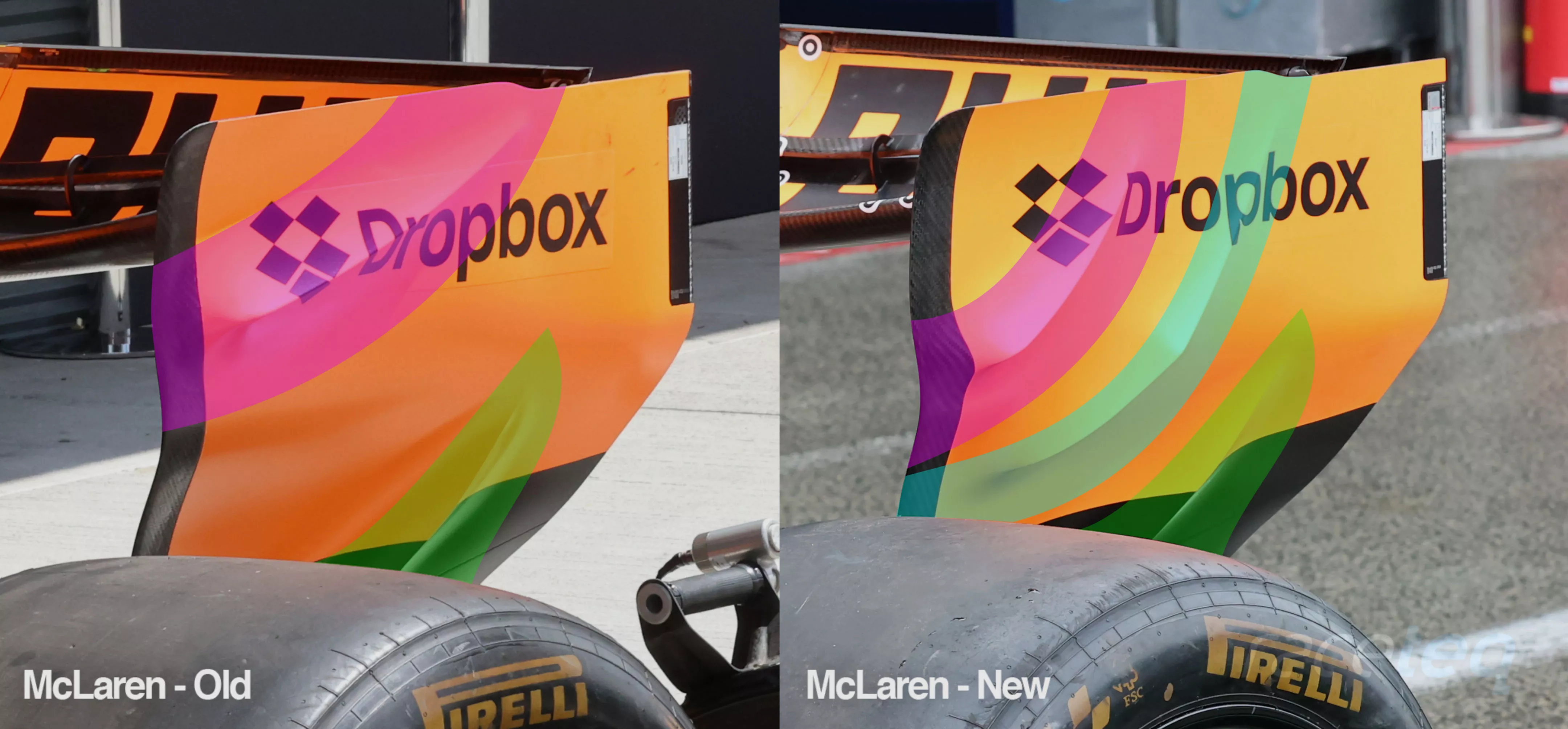
McLaren updated the design of their rear wing endplate for the Dutch Grand Prix, with an additional swage line added
McLaren continues to pursue more performance from the design of its rear wing endplate, as it added an additional upwashing swage line to the endplate’s portfolio at Zandvoort.
This is a trend that can be traced all the way back to the Monaco Grand Prix, in 2023, when Alpine and Aston Martin simultaneously introduced the solution.
There’s been numerous variations employed since, as teams grapple with how best to manage the structural integrity of the wing, against their aerodynamic demands, which must retain the dimensional criteria expected within the regulations.
This means that the thickness of the swage lines are often at the limit of what the regulations permit, whilst around them the endplate must be slimmer.
This is a challenge that’s made more difficult by the curved geometry of the endplate and is why we often see these swage lines in the upper and lower half of the endplate, rather than traversing the endplate’s curvature, as is the case with McLaren’s latest solution.
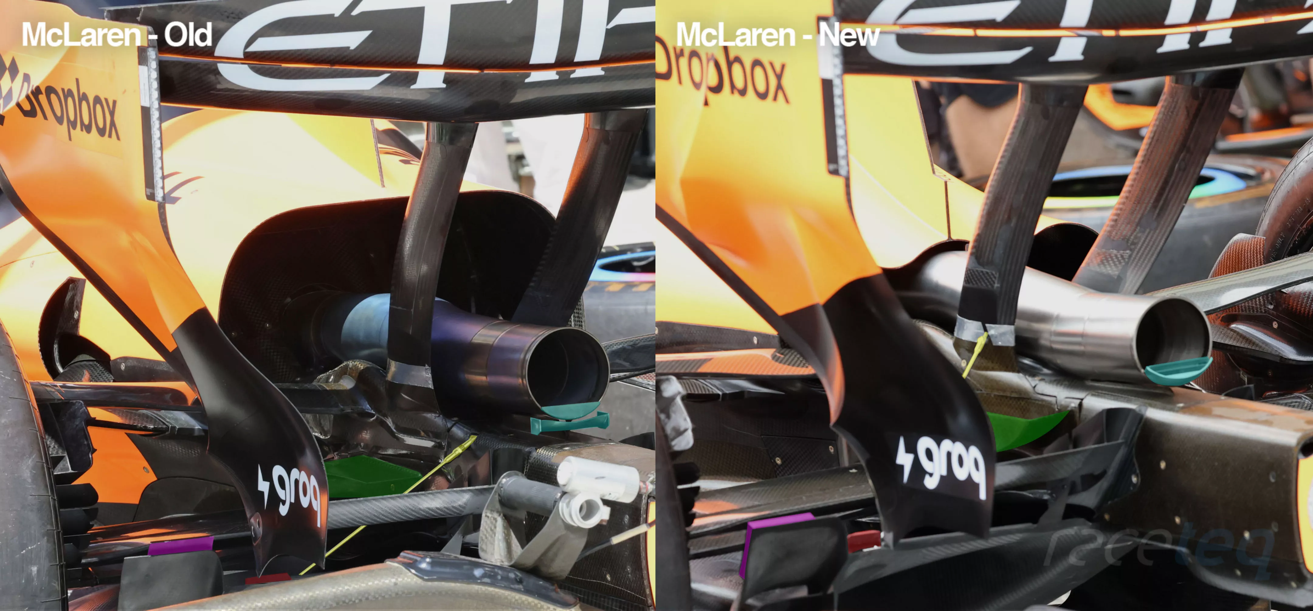
A comparison showing the numerous changes made by McLaren at the Dutch Grand Prix
It didn’t stop there for McLaren though, as it made a handful of smaller changes at the rear of the MCL40 to increase its performance further still.
Firstly, the exhaust bracket arrangement it first introduced in Miami (highlighted in cyan, above image) has been changed, taking on a slotted and upwashing geometry, rather than having a flat plate across the exhaust tip and winglet housed beneath.
These changes will have an impact on how the exhaust plume exits the tailpipe and how that impacts the other aerodynamic structures around it.
The trough-like appendage mounted on the side of the crash structure, which helps to direct the airflow upwards towards the car’s centreline has been altered (highlighted in green).
The additional flap mounted on the trailing edge of the floor winglet (highlighted in purple) has been moved across to the left-hand side of the surface and an endplate added.
Meanwhile, the floor support stay (highlighted in yellow) and the outer mini-Gurney flap (red arrow) have been moved in co-ordination with one another.
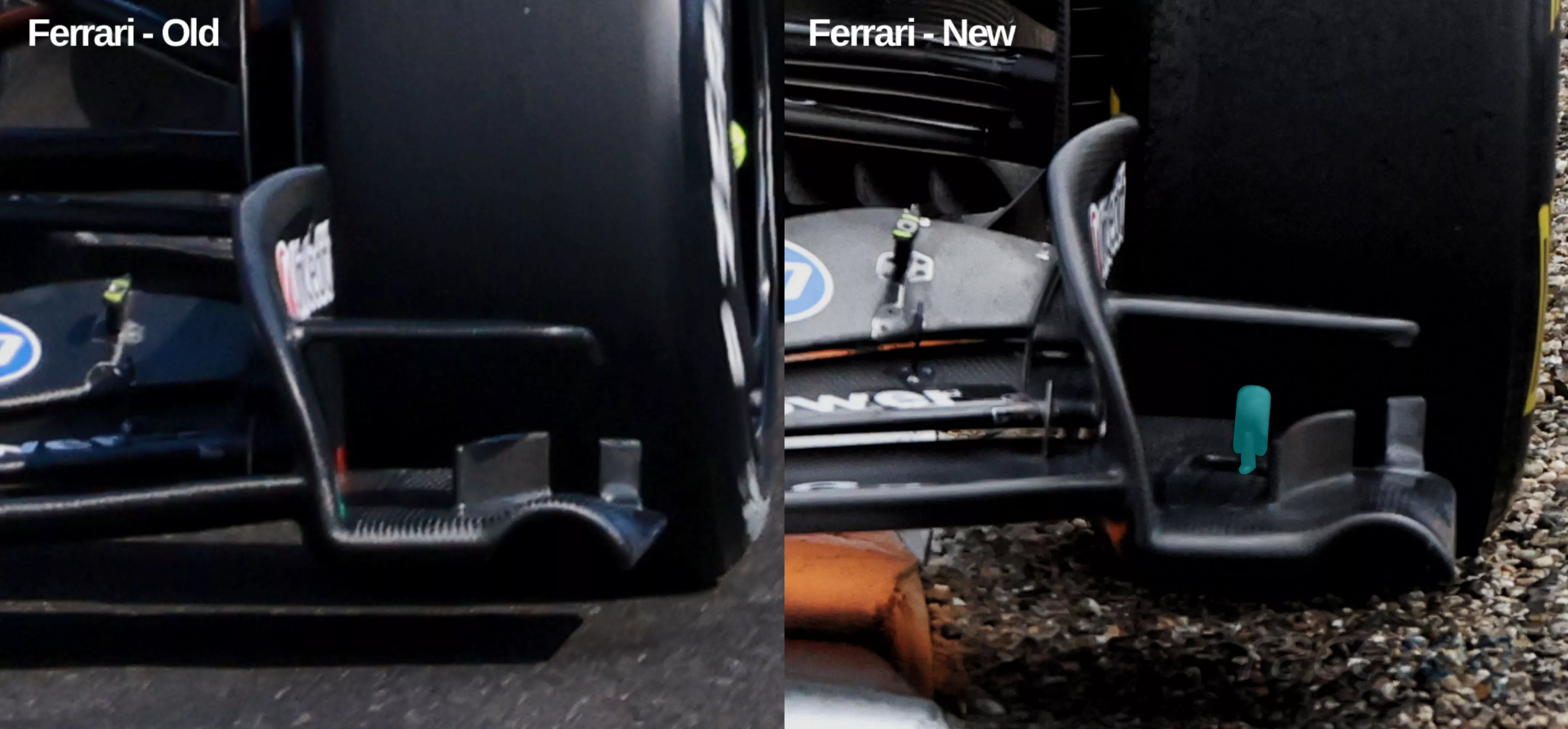
A comparison of the front wing endplate, footplate and ancillary furniture on the Ferrari SF-26
A small change for Ferrari at Zandvoort that didn’t make the car presentation document was a new placement for the infra-red tyre monitoring camera and pod, which the team doesn’t always use but has been mounted high up on the endplate when it has in the past.
However, at the Dutch Grand Prix the camera and pod found a new home, atop the footplate, which will clearly have an impact on the airflow’s behaviour in that region, even if the pod is relatively neutral it is angled up toward the tyre.
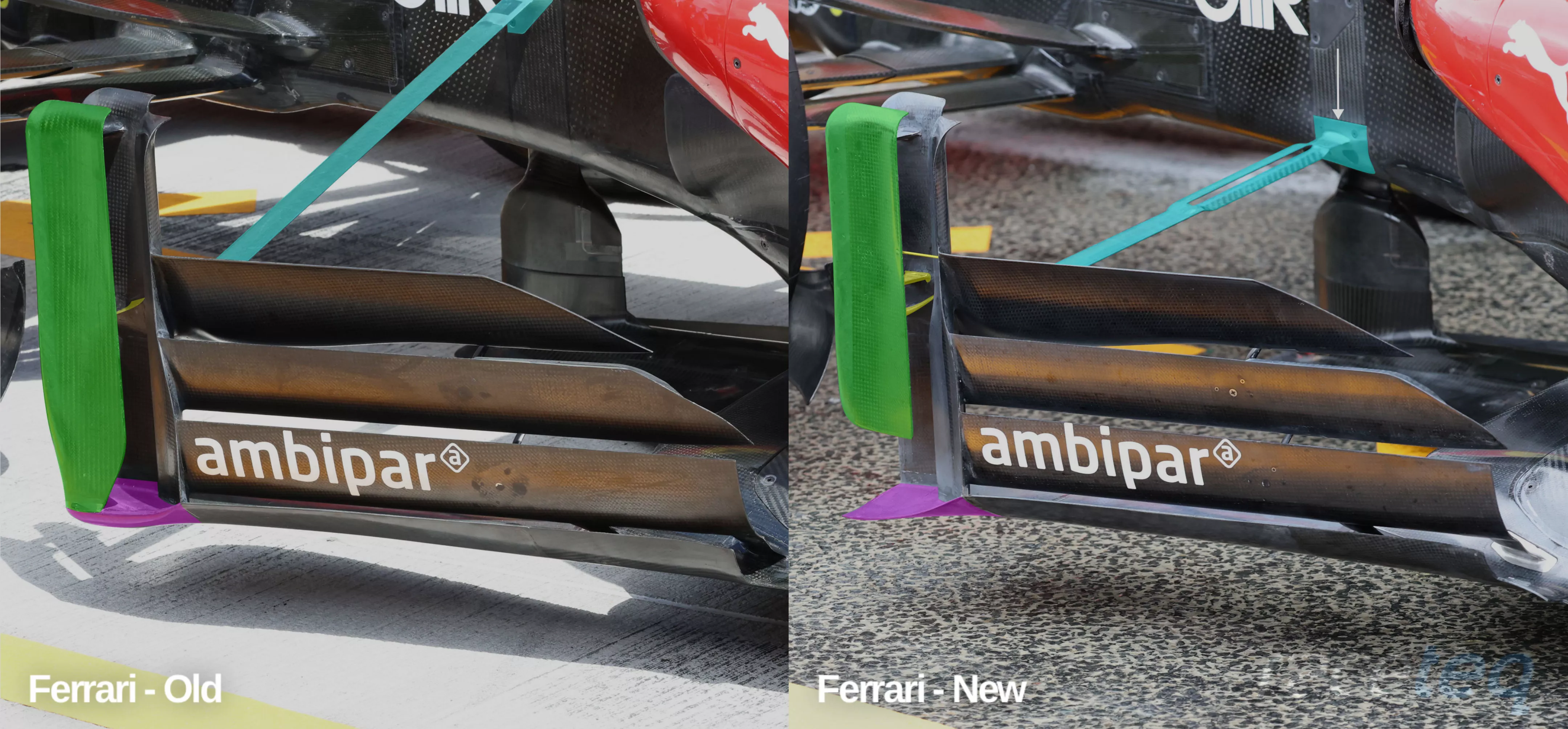
A comparison of the the floorboard and brace on the Ferrari SF-26
Ferrari also made some changes to its floorboard arrangement, with the outer skyscraper element (highlighted in green) cut down in order to free it from the floor’s axehead (purple highlight).
This provides the axehead with more aerodynamic authority, as it’s unencumbered by the vertical element, which now has its own vortex shedding surface on its lower edge but required some additional support elements to be added (highlighted in yellow) to prevent it from moving around too much under load.
The brace that connects and supports the floorboard arrangement with the chassis also underwent some reconstructive surgery, as its position was not only altered (white arrow), lowering it to the bottom of the chassis, a slot was also added at the chassis end to improve flow conditions across its chord.
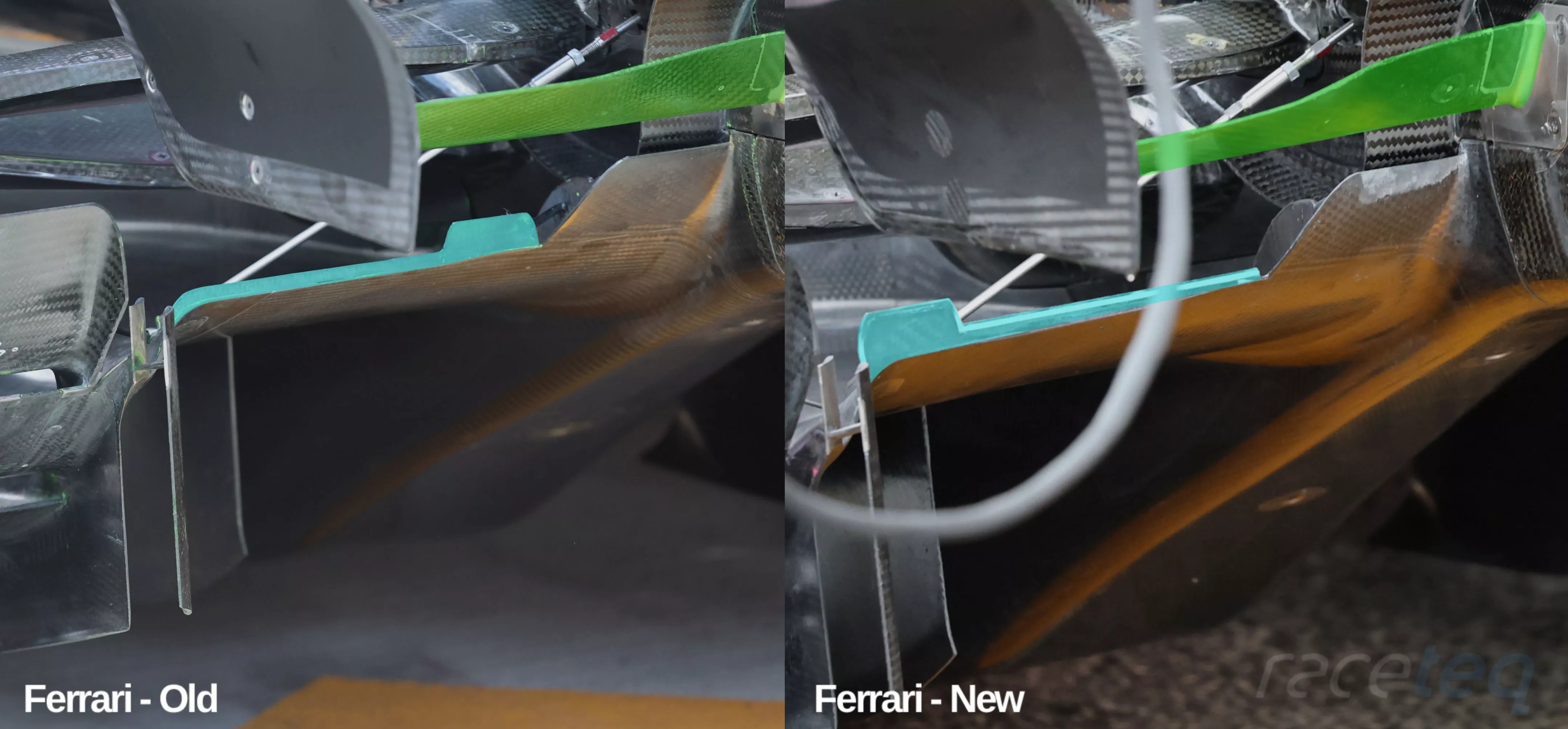
A comparison of the diffuser and beam wing on the Ferrari SF-26
Ferrari opted to adjust the spanwise loading capability of its beam wing arrangement at the Dutch Grand Prix (highlighted in green), creating a slimmer outboard section and deeper central section to better help balance the downforce and drag being generated.
Alongside those changes was an adjustment made to the position of the mini-Gurney flap arrangement on the trailing edge of the diffuser (highlighted in cyan). The larger tab-like section has now moved to the outer periphery of the diffuser, placing it nearer some of the ancillary items that have grown up around the edge of the assembly, in an effort to further enhance their effect.
Such is the rate of development in 2026, even at a race like the 2026 Dutch Grand Prix - which was somewhat disrupted by a sprint race that took away one practice session - did we see a bevy of upgrades with teams converging on Ferrari’s FTM solution while honing their cars for Zandvoort’s unique set of corners.